SESSION 1
FLOW PATTERNS IN OIL-WATER SYSTEMS: MODELLING AND EXPERIMENTS
Chairmen: D. Mewes, D.A. Siginer
OIL-WATER FLOW IN SMALL DIAMETER TUBES
P.A. Andreini, P. de Greef, L. Galbiati, A. Kuhlwetter, G. Sotgia
Energetics Department
Polytechnic of Milan
P.zza Leonardo da Vinci 32, 20133 Milano - Italy
ABSTRACT. Experimental results of flow patterns and pressure drop for oil-water
horizontal flow in small diameter tubes (3 mm and 6 mm internal diameter) are reported.
Oil-to-water viscosity ratios from about 560 to about 1300 were investigated.
Demineralized water and different kinds of oils were sent through two positive
displacement pumps to a mixing chamber. A thorough mixing of the two liquids, which
served to eliminate entrance effects on the test section, was attained in a calming section
(L/D=200) before entering the test section. Special fittings allowed both the calming
section and the test section to be lined up with them so that the flow saw no change in
diameter. The small diameter tubes for the test sections were made of precision glass, steel,
copper and PVC. The pressure at the beginning of the test section was measured using a
pressure transducer. Fluid temperatures were measured using J-thermocouples.
Measurements were taken at a temperature ranging from 15oC to 25oC. Oil and water
flowrates ranged from 0.9 10-7 m3/s (0.32 l/h) up to 9.4 10-6 m3/s (33.9 l/h). As far as flow
regimes are concerned, a series of flow patterns was observed and was reported in terms of
dispersed, intermittent (slug, plug) and annular flows. Flow regime photographs were
taken using a specific camera (equipped with a 1/4000 s electronic flash). It is worth
mentioning that oil was observed, in most of cases, to flow in the core of the pipe and
water flowed around the perimeter; in these conditions, sensible pressure loss reductions
(up to about 1/250), in respect to the pressure drop of the oil flowing alone at the same
flowrate, were observed.
Tube wall material was found to influence the flow patterns at water-to-oil flowrate ratios
relatively low (less than 0.2-0.3). In particular, in these conditions, an "inversion" of
annular flow pattern was observed (oil next to the wall and water flowing in a core) with
steel, copper and plastic tubes. In addition to the experimental results, theoretically based
transition criteria for the flow patterns and pressure drop correlations (derived from
literature) are discussed. In particular, Brauner models for flow regime transitions seem to
match experimental results fairly well. As far as pressure drop evaluation is concerned,
Brauner theoretical predicitions have been empirically corrected using experimental
results.
EFFECT OF MIXERS ON FLOW PATTERN AND PRESSURE DROP IN HORIZONTAL OIL-WATER PIPE FLOW
A. Soleimani, C. J. Lawrence, G. F. Hewitt
Department of Chemical Engineering, Imperial College
London SW7 2BY, UK
Cocurrent flow of two immiscible liquids is encountered in a variety of industrial
processes and petroleum transportation. This paper reports a series of experiments
to investigate the flow pattern occurnng in liquid-liquid flow in a horizontal nominal
one inch tube. Experimental results are presented for Kerosene (EXXOL D80) and tap
water at room temperature. A STATFLOW in line static mixer (Kenic) was placed at the
beginning of the test section. The static mixer was made from stainless steel with one inch
nominal bore and 0.275m length and could be fitted with up to five helical elements.
A short transparent pipe 3cm long, made from acrylic, was used for visualisation purposes
in the stainless steel test section. In these experiments the focus was on determining the
flow pattern and pressure drop with and without the mixer. The parameters which control
the flow pattern are the volumetric flow rate of each phase, the density and viscosity of
each phase, the pipe geometry and inlet design, the surface tension and possibly other interfacial
effects. The different flow patterns were recorded by high speed video camera. Generally
six types of flow regime were observed in this experiment. The flow regimes are
compared with the experimental maps given by Angeli (1996), Arirachakaran (1989) and
Nadler(1995). The pressure gradient was measured for each point on the flow regime map
and an attempted was made to correlate changes in pressure drop with change in flow pattern.
The effects of the mixer on the pressure gradient were investigated in dispersed flow regime.
Two peaks in pressure drop appeared when more than two mixer elements were
used. The first peak always appears in dispersed flow and is associated with phase inversion,
while the second peak was found to depend on the number of elements in the mixer
and position of the pressure gauges along the test section. It has been noted that the number
of elements in the static mixer has an effect on the drop size and the emulsion structure.
The flow configuration corresponding to the second peak was also observed for lower
mixture velocities (between 0.5 m/s to 1.5 m/s) along with two other patterns (stratified
mixed/oil layer and three layer). It was noted that the pressure drop was higher in this flow
regime than the other two.
PRESSURE DROP, FLOW PATTERN AND SLIP FOR TWO PHASE CRUDE OIL/WATER FLOW:
EXPERIMENTS AND MODEL PREDICTIONS
Arne Valle, Ole Harald Utvik
Norsk Hydro ASA, Research Centre Porsgrunn
P.O. Box 2560, N-3901 Porsgrunn, Norway
ABSTRACT Flow experiments have been conducted in a 3 inch ID flow loop of steel
at a length to diameter ratio of 1100. The fluids were light crude oil from the North
Sea 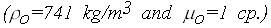 and synthetic formation water. The fluids were saturated with
hydrocarbon gas at 105 bar and 70 oC. The water-cut was varied between 0 % and
100 % at three constant liquid flow rates. Pressure drop, in-situ phase fractions and
the flow patterns were measured. An analysis of the experimental data is presented. A
comparison between the experimental observations and model predictions have been
performed. The main conclusions are as follows; and synthetic formation water. The fluids were saturated with
hydrocarbon gas at 105 bar and 70 oC. The water-cut was varied between 0 % and
100 % at three constant liquid flow rates. Pressure drop, in-situ phase fractions and
the flow patterns were measured. An analysis of the experimental data is presented. A
comparison between the experimental observations and model predictions have been
performed. The main conclusions are as follows;
- Dispersed oil continuous flow exists for water-cut below 45 %. The pressure drop relative to single phase flow increases monotonically with increasing water-cuts up to the point of inversion. The relative increase of pressure drop is most pronounced at the lowest flowrate. The mean velocity of dispersed droplets is higher, compared to the continuous oil. The slip is highest for the highest flowrate. The velocity field is less homogenous, compared to a turbulent single phase velocity profile.
- Stratified flow occurs at water-cut above 45 % for all flow rates. The pressure drop is approximately constant and close to that of single phase flow conditions.
- A homogenous pressure drop model combined with the Pal&Rhodes model for the dispersion viscosity predicts the pressure drop quite well for the higher flowrates. The model under predicts the pressure drop for the lowest flow rate.
- There is a significant inconsistency between pressure drop and slip ratio for stratified flow by applying a two fluid model. In order to match both pressure drop and slip the ratio of the wall friction factors in the oil and water continuous zones is approximately a factor of 7.5. The friction factor should then be relatively higher, compared to single phase flow analogy, in the oil zone and a significant drag reduction should be assumed in the water continuous zone.
PRESSURE DROP MEASUREMENTS IN OIL AND WATER PREWETTED PIPES
Panagiota Angeli*, Geoffrey F. Hewitt**
*Department of Chemical and Biochemical Engineering,
University College London,
London, UK
**Department of Chemical Engineering and Chemical Technology,
Imperial College of Science, Technology and Medicine,
London, UK
1. INTRODUCTION
Liquid-liquid flows have many applications in a diverse range of process industries and particularly in
the petroleum industry. The pressure gradient in such flows depends on the flow regime as well as
the properties of the pipe wall (roughness and wettability)1. Due to the different affinities of liquids
to materials, the wetting characteristics of the wall in particular can significantly affect pressure
gradient. Pipe wall wettability can be affected by the wetting of the pipe with one of the liquids prior
to the multiphase flow. Despite this, the wall properties are not usually taken into account and
although the main application of such flows has been in the transport of oil-water mixtures in steel
pipelines, most of the experimental work has been carried out in glass or acrylic pipes.
2. EXPERIMMENTAL PROCEDURE
The present study was aimed at establishing whether the prewetting of a pipeline prior to the
multiphase flow with one of the process liquids would affect the pressure gradient during oil-water
flow. Pressure gradients were measured in two 1 inch nominal bore test sections made from stainless
steel and acrylic resin respectively. Two pipes were used in order to examine the effect of the
different pipe material on the flow phenomena. The steel pipe is rougher than the acrylic one and also
has very different wetting characteristics. The test fluids used were tap water and kerosene
(EXXSOL D80 with 801 kg/m3 density and 1.6 mPa.s viscosity). Measurements of the contact
angles for water drops in oil and for oil drops in water2 revealed a dependence of the contact angle
on the pipe material and the fluid which had prewetted the pipe wall.
Experiments were performed at mixture velocities 2.2 m/s and 1.3 m/s. Initial runs, with no
prewetting of the pipes, covered water volume fractions from 0% to 100%. When prewetting was
used, experiments were performed at the higher velocity for 40% and 60% water fraction and at the
lower velocity for 50% water fraction. In a typical run with prewetting, the pipe was filled with one
of the liquid phases and was left overnight. The next day, the liquid that had wetted the pipe was run
for 10 min at the flowrate required for the multiphase flow. The other liquid was then introduced at
its required flowrate and the multiphase flow was run for 1-1.5 hours. At the end of this period the
initial single phase was run alone in the pipe for ten minutes and after that the other phase was again
introduced. The multiphase flow was run for an additional 25 min before again being replaced by the
initial single phase flow. Pressure gradients were recorded during this time.
3. RESULTS
At the lower velocity the flows were either dispersed or separated with inter-entrainment at the
liquid-liquid interface. At the higher velocity the flows were fully dispersed and phase inversion
appeared at around 40% water volume fraction. The experiments revealed that the pressure gradients
were always higher in the steel than in the acrylic pipe, more than what would be expected from their
roughness difference. This difference could be due to the different wettabilities of the two materials.
Also during phase inversion there was an increase in pressure gradient, which was more prominent in
the steel pipe.
The results, when prewetting of the pipes was used, can be summarised as follows.
- Experiments at 2.2 m/s mixture velocity and 60% water fraction (Fig. 1): Here the flow is water continuous (mixture after phase inversion). In both pipes prewetting of the tube material with water resulted in higher pressure gradients during the two-phase flow.
- Experiments at 2.2 m/s mixture velocity and 40% water fraction (Fig. 2): Here the flow is oil continuous (just before phase inversion). In both pipes the dependence of the pressure gradient on the prewetting phase is small, but the oil prewetting gave slightly higher pressure gradient.
It was observed that these changes in pressure gradient relate to the changes in contact angle resulting from prewetting of the pipes. An increase in contact angle between the dispersed drops and the wall gives an increase in pressure gradient and vice versa.
- Experiments at 1.3 m/s mixture velocity and 50% water fraction. Here the flow pattern in the steel pipe is dispersed with water as the continuous phase, while in the acrylic pipe is stratified with high degree of interfacial mixing. In the steel pipe water prewetting gave higher pressure gradients than oil prewetting, possibly for the same reason as for the higher velocity. On the contrary in the acrylic pipe there was no significant effect of prewetting on the pressure gradient. In this case where both phases are continuous possibly any effect of prewetting is counteracted by the presence of both liquids in contact with the pipe wall.
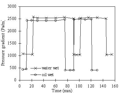
Figure 1: Pressure gradient in the steel pipe at 2.2 m/s and 60% water fraction.
Figure 2: Pressure gradient in the steel pipe at 2.2 m/s and 40% water fraction.
Pipe wall properties and especially the wetting characteristics can therefore affect pressure gradient
in liquid-liquid flows and should be considered in the application of data from the usual laboratory
case of acrylic tubes to the more practical case of steel tubes.
4. REFERENCES
- Angeli P. and Hewitt G.F., Pressure gradient in horizontal liquid-liquid flows, submitted to Int. J. Multiphase Flow, 1996.
- Valle A., Private communication, Norsk Hydro a.s., 1995.
|
