|
Session 13
HEAT EXCHANGERS
Chairman: L. F. Fletcher
ADVANCES IN NUMERICAL ANALYSIS OF HEAT TRANSFER AND FLOW FRICTION CHARACTERISTICS OF COMPACT HEAT EXCHANGERS SURFACES
R. Shah
Compact Heat Exchangers (CHEs) are characterized by large heat transfer surface area per unit volume of exchanger, resulting in reduced space, weight, and usually reduced energy requirements and cost compared to conventional designs such as shell-and-tube exchangers. Plate-fin, tube-fin, plate-and-frame, welded plate, and printed circuit exchangers are some examples of compact exchangers. Typically, a compact heat exchanger has a heat transfer surface area density in excess of 700 m2/m3 for gas streams, and over 400 m2/m3 for liquid and two-phase streams.
The objective of this paper is to provide a comprehensive state-of-the-art review on numerical studies of single-phase heat transfer and flow friction characteristics of compact heat exchanger surfaces; and where experimental data available, provide specific comparisons to verify the accuracy of numerical work. The surfaces include (1) various fin geometries including plain, wavy, louvered, offset strip fin, and others used in plate-fin exchangers, as well as those fin geometries used in tube-fin exchangers, (2) narrow noncircular and circular channels that are used in compact heat exchangers and regenerators, and (3) stamped plates used in plate heat exchangers.
Starting with description of some of the complex flows in such surfaces, it is explained that flows in compact heat exchanger surfaces are dominated by swirl flows or flow separation, recirculation and reattachment generally encountered in the wake regions of surface interruptions. Such swirl flows, unsteady laminar flows or low Reynolds number turbulent flows are difficult to analyze numerically accurately because of the lack of good models. This is the reason for very slow progress of numerically analyzing compact heat exchanger surfaces.
After posing the numerical analysis problem of compact heat exchanger surfaces, briefly described are different methods used in the numerical analysis of compact heat exchanger surfaces with appropriate comments on the advantages and limitations. This should provide an idea to reader what has been tried and will give an opportunity to some researchers to try some new techniques in the future to solve the complex flow and heat transfer problems.
The body of the paper covers all numerical work reported in the literature (that authors could locate) on the CHE surfaces, individually for each surface, describing numerical analysis in sufficient details, and providing comparisons with experimentation where available. Then discussion is presented on (1) the physics of flow and heat transfer phenomena based on the insight gained from the numerical analysis, (2) the limitations of current numerical methods for the analysis of CHE surfaces, (3) the proposed mode of research that combines numerical analysis, sophisticated experimentation on the small sample fin geometries and performance testing of actual heat exchanger cores. Finally, summarized are concluding remarks and proposed areas of research.
A PARAMETRIC STUDY OF AN ANNULAR HEAT EXCHANGER WITH APPLICATION TO SOLAR THERMOSYPHON SYSTEMS
Nasr A.
Morrison G. L.
Behnia M.
Abstract is unavailable.
NUMERICAL MODELLING OF A CERAMIC HEAT EXCHANGER
Dr P Langston* and Prof J Swithenbank**
*Stone & Webster Eng Ltd, 500 Elder Gate,
Central Milton Keynes, United Kingdom
**Department Of Chemical Engineering,
The University Of Sheffield, Mappin Street, Sheffield, U.K.
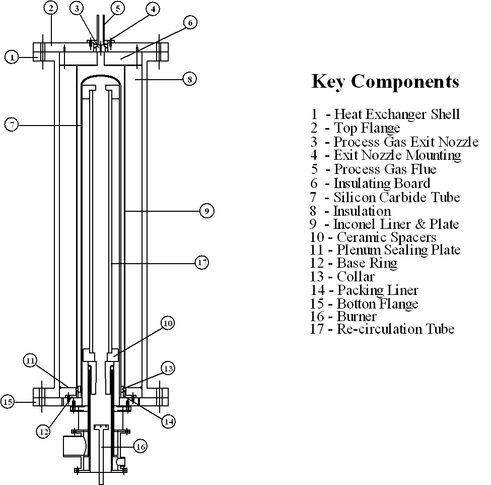
An experimental ceramic heat exchanger, the UHX (ultra temperature heat exchanger), was developed at The University of Sheffield to study heat transfer at temperatures above 1000°
C, Figure 1. Designed for application to advanced power generation cycles1, the UHX used a 60 kW natural gas fired burner to heat process gases at 5 barg pressure to temperatures exceeding 1200°
C.
Slip cast siliconised silicon carbide (SiSiC), a fully dense, high strength, fine grained ceramic was used as the heat transfer tube material, having a significantly higher thermal conductivity than superalloys at elevated temperature. SiSiC is, however, restricted to maximum operating temperature of 1250°
C, as loss of strength is experienced due to volatilisation of free silicon present in the material structure.

Figure 1: The UHX experimental ceramic heat exchanger
To reduce stress process gas was injected around the exterior of the ceramic tube, placing the ceramic material in compression. Although many ceramic heat exchanger variants have been constructed in the past, they have invariably placed the ceramic material in tension. Consequently, ceramic heat exchangers have traditionally been restricted to low pressure differentials across the ceramic assembly due to a tendency for catastrophic brittle failure of the test module. Operation under compression, and the development of specialised tubesheet seals reduces the occurrence of such brittle fracture in the UHX.
To gain a greater understanding of the experimental results obtained from UHX operation a numerical fluid dynamic model of the rig was constructed. FLUENT/BFC v4.23 computational fluid dynamics (CFD) package was used as the numerical tool, having the ability to model heat and fluid flow with chemical reaction.
A 20,000 cell axisymmetric, two dimensional, curvilinear grid was constructed with a simplified burner geometry. By giving the process fluid annulus a computational width of 9 cells and the SiSiC tube a thickness of 5 cells, temperature profiles within the process fluid annulus and heat transfer tube could be studied in both the width and length dimensions. All structural components within the UHX were modelled as distinct wall types, set with temperature dependent thermal conductivity's2,3.
The FLUENT code approximates a solution to the Navier-Stokes equations by a finite difference technique, using a staggered grid. A moment method was used to close the turbulent Navier-Stokes equations by use of Reynolds Stresses. Turbulent chemical reaction rates were modelled by the Eddy Break-up model. The Discrete Transfer Radiation Model (DTRM) with variable absorption coefficient (dependent on the local concentrations of the species H2O & CO2) was activated to include radiation heat transfer in the enthalpy continuity equation.
Quantitative validation of the numerical model was achieved by comparing process air and SiSiC surface temperature predictions to measured data. Air temperatures predicted in the centre of the process air annulus by the numerical model compared very favourably with the experimental data obtained. Outer surface ceramic temperature predictions were not as concordant, however, being consistently higher than that measured. Visual inspection revealed that during operation the surface thermocouples had become detached from the SiSiC tube. This was caused by the distortion of the metallic Inconel liner, highlighting the importance of material creep properties in UHX design.

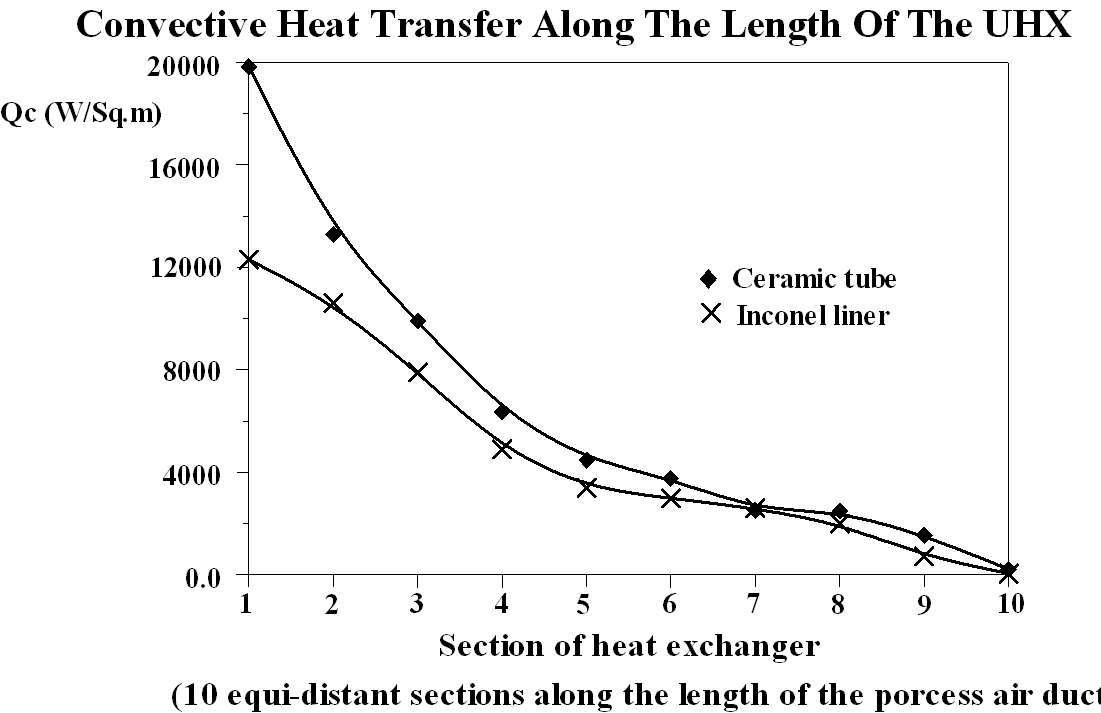
Figure 2: Convective heat flux to the process air
As air does not readily absorb radiation, radiant heat transfer through the air side of the exchanger was absorbed and reflected by the Inconel liner. After studying the temperature profile throughout the heat exchanger, it was clear that process air received convective heat from both sides of the process air annulus. Hence, the liner acted as a floating temperature wall, receiving and emitting radiation from the ceramic tube while closing the heat balance by transferring convective heat to the process air.
As the liner is at a lower temperature than the ceramic tube the liner provides a smaller proportion of heat to the process air than the ceramic tube in every section of the UHX. However, as the distance from the process air inlet is increased the proportion of heat from the liner increases. Thus the liner is a significant source of heat to the process air (Figure 2), and could be significant with respect to heat transfer augmentation in an industrial UHX design.
REFERENCES
- Swithenbank, J. et al, “New Developments IN Power Generation”, Technologies For A Cleaner Environment, Seminar, Cuernavaca, Mexico, 1995.
- Morrel, R., "Handbook Of Properties Of Technical & Engineering Ceramics - Part 1 An Introduction For The Engineer And Designer", National Physical Laboratory, 1987.
- Hepworth, "M.A., Processing, Properties and Applications of Structural Silicon Carbides", British Ceramic Proceedings No. 46, Advances in Engineering With Ceramics, p113-125, 1990.
LAMINAR FORCED CONVECTION ON THE SHELL-SIDE OF A FINNED DOUBLE-PIPE HEAT EXCHANGER
K.S. Syed*, G.E. Tupholme*, A.S. Wood* and P.J. Heggs**
*Department of Mathematics
University of Bradford, Bradford BD7 1DP, UK
**Department of Chemical Engineering
UMIST, PO Box 88, Manchester M60 1QD, UK
The need to design more efficient and compact heat exchangers has led to the technique of attaching fins as additional heat transfer areas. In this way the heat transfer coefficient between the solid surface and the fluid can be increased to enhance the performance of the heat exchangers. The present work presents a first mathematical study of the steady laminar forced convection in the annular region between two concentric circular pipes with tapered longitudinal fins distributed uniformly around the shell side of the inner pipe, the so-called double-pipe heat exchanger (DPHE), as depicted in Figure 1. The fin sides form radii of the circular geometry and the tips are circular arcs concentric with the pipes.

Figure 1: Geometry of a finned double-pipe heat exchanger.
Various heat transfer characteristics have been investigated subject to a constant wall axial heat flux, with a uniform temperature condition at the (inner) heat transfer surface, and an adiabatic condition at the outer pipe. The thermal assumptions for the solid heat transfer surfaces are that the axial conduction is zero, while in the radial and circumferential directions there is infinite conductivity. On the outer pipe surface there is no conduction.
The governing momentum1and energy equations in the fluid are solved numerically assuming viscous, incompressible flow, constant fluid properties and negligible viscous-energy dissipation in a region sufficiently far from the entrance for fully-developed profiles to have been attained. The numerical procedure adopted is based upon finite difference replacements of the governing equations and conditions, with iterative refinement being used to solve the resulting algebraic equations. A detailed discussion of the numerical algorithm which has been developed by Syed, Tupholme and Wood2 for efficiently solving such a class of elliptic boundary value problems up to any desired order of accuracy has been accepted for presentation elsewhere.
The fins' influence on the flow domain has been investigated for variations in the following geometrical parameters; the number of fins, the fin height and the half-fin angle. In the full paper, results are presented illustrating both the local and average behaviour of important transport characteristics including Nusselt numbers, the product of the fanning friction factor with the Reynolds number, and heat transfer rates.
In order to compare the performance of a finned DPHE with an unfinned DPHE a common geometric scale, which is the annular diameter of the double pipe, is used. For illustration, the results shown in Table 1 (for a value b
=0) give values of the flow-area goodness factor3 for various configurations of the finned DPHE. The case of zero fin height corresponds to the finless geometry. Higher values of the flow-area goodness factor indicate improved performance.
| NF | FIN HEIGHT
| | 0.0 | 0.1 | 0.2 | 0.3 | 0.4 | 0.5
| | 3 | 0.295 | 0.295 | 0.300 | 0.306 | 0.312 | 0.316
| | 6 | 0.295 | 0.295 | 0.318 | 0.362 | 0.401 | 0.418
| | 9 | 0.295 | 0.294 | 0.323 | 0.401 | 0.488 | 0.523
| | 12 | 0.295 | 0.291 | 0.314 | 0.408 | 0.547 | 0.602
| | 15 | 0.295 | 0.287 | 0.298 | 0.390 | 0.581 | 0.659
| | 18 | 0.295 | 0.282 | 0.280 | 0.359 | 0.595 | 0.699
| | 21 | 0.295 | 0.277 | 0.263 | 0.325 | 0.593 | 0.728
| | 24 | 0.295 | 0.273 | 0.249 | 0.292 | 0.579 | 0.750
| | 27 | 0.295 | 0.268 | 0.236 | 0.263 | 0.556 | 0.766
| | 30 | 0.295 | 0.265 | 0.226 | 0.239 | 0.525 | 0.779
|
Table 1: Flow-area goodness factor comparison.
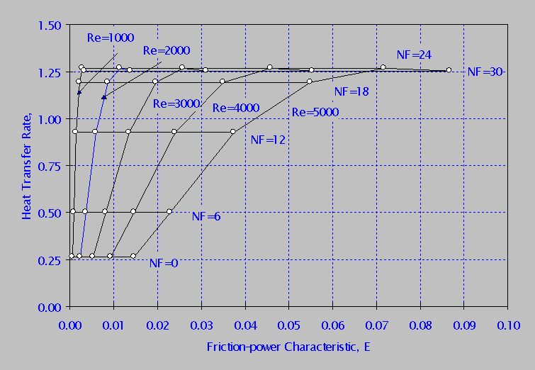
In Figure 2 values of the heat transfer rate, H, are plotted against values of the friction-power characteristic4, E, for selected values of NF and a range of Reynold’s numbers (from 1000 to 5000).
For fixed NF there is no change in H for a wide range of Reynold’s numbers. However, increasing the number of fins improves the heat transfer performance of the DPHE for a fixed value of E, up to an optimum value.
The numerical methodology presented in this paper, when applied to the annular model without fins and to the problem of internally finned tubes, shows excellent agreement with the results of other authors. The study shows that whilst average characteristic values can be used to assess the global performance of heat-exchanger designs, in order to improve design methodology it is necessary to use local characteristic variations.
Finally, it is indicated that the thermal boundary conditions used in this paper, which are typical of a majority of studies seen in the literature, are not a realistic description of the physical situation. On-going work, based upon the solution of a conjugate two-dimensional model problem, is being undertaken with a view to substantiating these intuitive misgivings.

Figure 2: A comparison of heat transfer and friction-power characteristics for varying numbers of fins, NF, and a range of Reynold’s numbers.
REFERENCES
- Kettner, I.J., Degani, D. and Gutfinger, C., Numerical Study of Laminar Heat Transfer in Internally Finned Tubes, Numerical Heat Transfer, Part A, Vol. 20, pp 159-180, 1991.
- Syed, K.S., Tupholme, G.E. and Wood, A.S., Iterative Solution of Fluid Flow in Finned Tubes, Numerical Methods for Laminar and Turbulent Flow Conference, Swansea, July 1997.
- Shah, R.K. and London, A.L., Laminar Flow Forced Convection in Ducts, Academic Press, London, 1978.
- Kays, W.M. and London, A.L., Compact Heat Exchangers, McGraw-Hill, New York, 1984.
|

