POSTER SESSION
PLASMA TORCHES
WATER STEAM PLASMATRON FOR HAZARDOUS WASTE TREATMENT
Romualdas Kezelis, Romualdas Juskevicius, Vladas Mecius
Plasma processing laboratory,
Lithuanian Energy Institute, Breslaujos 3, Kaunas, Lithuania
Some toxic waste materials, such us, some organic compounds of chlorine, when burnt at temperatures lower than 1300 - 1500 oC do not break up and new toxic substances as dioxins, furans and other are formed. To decompose them completely temperature must be raised to over 1800 oC1. This can be done using, plasmachemical reactor, which receives hot gas stream from plasmatron heated up to temperature T = 2000 - 3000 K.
While organic compaunds are heated without or there is insufficiently oxidizer (air, water steam) the pyrolysis and gasification take place. If there are enough oxidizer, we have burn-up process 2.
In some cases water steam plasma is used for waste treatment. Properties of plasma differ considerably from ones of air plasma. Enthalpy of water steam at high temperatures exceeds air enthalpy several times. Utilization of air plasma can produce toxic nitrogen oxides and cyanic compounds, while water steam plasma is clean for environment. Therefore, possibilities of application of water steam plasmatron for hazardous waste treatment was considered in this work.
For this purpose water steam plasmatron was designed, built and tested, its power and thermal performance data measured (fig.l.). Some experiments of decomposing organic waste substances by water steam at high temperatures were carried out.
 Parameters of the plasmatron varied with following limits: magnitude of current I=30 to 180 A, voltage U=90-240V, power of the plasmatron N = 6-20 kW, water steam flow rate G = 0.6 - 1.7 gs-1. Average mass temperature of flow at plasmatron outlet varied within limits of T = 2000 - 3200 K.
The cathode of the plasmatron was made of tungsten and the anode was made of copper. Water steam is supplied tangentially through isolating rings of glass textolyte. All parts of the plasmatron were cooled by water. To prevent the condensation of steam on the cold electrodes, the last section of the anode is cooled not by water, but by water steam. In this section steam is overheated and fed the inwards in yhe plasmatron. The bulk water steam temperature was determined from heat balance. Other measurements included electric parameters and flow rate of water steam. For hazardous waste treatment a special reactor was built and connected to the plasmatron. It appears as the stream reactor of 1.8 m length and 0.2 m diameter with a line of ZrO2. Results on gas dynamic and heat transfer for high temperature water steam and air flows in reactor has been analysed.
Our measurements show that to 100 A plasmatron operate in dropping range of voltage-current properties (fig.2). When arc current is more than 100 A, the voltage is constant.

Most toxic wastes are organic compounds, therefore, in the first place decomposition of wood as organic substance by water steam plasma was carried out (fig.4). Our experiments revealed, that already beginning with values of temperatures 600 to 1000 oC not only decomposition of organic substance occurs but also wood carbon gasification takes place. In this case synthetic gas (CO+H2) is produced. In addition, experiments related to detoxication of some organic acids were carried out. Yhe experiments and calculations3 shows, that organic materials, when oxidizer is water steam with temperature T =1200-3000 K, breaks up into gases, containing only carbon dioxide and hydrogen. If materials decomposed contain nitrogen, molecular nitrogen is produced.

During experimentation energy consumption by plasmic aste processing was determined (fig.5). There is a trend for energy consumption to increase with temperature. The costs of waste treatment by plasma technology are higher. The plasma method of destroying toxic materials has been useful in cases when very high temperatures are necessary to break its up and traditional combustion causes harm to humans and environment, or in cases when the mixture of hazardous substances is unable to identify.
REFERENCES

| .
|
NUMERICAL ANALYSIS AND EXPERIMENT ON A PLASMA TORCH WITH HOLLOWED ELECTRODES FOR HAZARDOUS WASTE TREATMENT
Min Hur, Hong Cho, and Sang Hee Hong
Department of Nuclear Engineering, Seoul National University, 151-742, Seoul, Korea
Waste treatment is certainly one of the most promising areas of thermal plasma application, which
aims either at the reclamation of waste materials for recovering higher valued products or at the
destruction of toxic wastes and the generation of environmentally safe by-products. The high
power plasma torches have been widely used for the incineration of waste materials to pyrolyze
organic toxins and to vitrify the solid materials through their volume reduction in a nonleachable
compact state.
In this study, the thermal plasma characteristics of a high power nontransferred plasma torch with
hollowed electrodes shown in Fig. 1 are numerically and experimentally investigated in ambient
atmosphere of normal pressure by analyzing the distributions of plasma temperature, velocity and
mass flow rates and by making use of a similarity criterion1 predicting operation conditions of high
power plasma torches, respectively.

In the numerical analysis, typical assumptions of steady state, axisymmetry, local thermodynamic
equilibrium (LTE) and optically thin plasma are adopted in a two-dimensional MHD modeling of
thermal plasma. A control volume method and the modified SIMPLER algorithm2 are used as
numerical scheme for solving the governing conservation equations of mass, momentum, and
energy along with the equations describing the K-e model for turbulent effects, the current
continuity for arc discharges and Biot-Savart's law for applied magnetic fields generated by
solenoid coils for rotating arc spots around electrode surfaces to reduce their erosion.
Positions of arc spots on cathode and anode electrodes are determined by using a cold flow
analysis3 and Steenbeck minimum principle4, respectively. The calculated results show that the arc
length between cathode and anode spots becomes longer as electrode diameter and gas flow rate are
increased and input current is decreased.
The distributions of plasma temperature, velocity, and mass flow rate are calculated in various
operating conditions such as gas flow rate, input current, and electrode geometry. As a typical
numerical illustration, the distributions of temperature and velocity vector for air plasma are shown
in Figs.2 and 3. When arc gas flow rate injected from a vortex chamber is increased, the
temperature of air plasma is lowered and its velocity and mass flux show a rising tendency. The
numerical calculations also indicate that the radial profiles of plasma temperature have a tendency
to spread radially, but those of velocity and mass flux are decreased rapidly as the electrode
diameter becomes larger. When the operation current rises, the calculated temperature and velocity
of thermal plasma are increased, but the mass flux is slightly reduced.

A small-scale plasma torch of hollowed-electrode type designed and fabricated in the authors'
laboratory has been used in the experiments for predicting operational characteristics of high power
plasma torches by a similarity criterion, which represents a relationship among arc voltage U,
current I, gas flow rate G, cathode diameter dc, and anode diameter da, as follows1,3:

where s0, h0 , and m0 are the electrical conductivity, enthalpy, and viscosity of plasma gas,
respectively, at a temperature corresponding to an electron concentration of 1 % in the plasma.
The similarity criterion is experimentally determined by such a way that the variations of voltage
with arc current, gas flow rate, and electrode diameter, as measured in Fig. 4, are expressed by the
above semiempirical relationship established by finding the parameters, K, s, b, g and d.
From Fig. 4, one can obtain the following experimentally determined values of parameters for similarity
criteria :

Once the simulation results obtained from the numerical modeling on various operating conditions
are incorporated with the experimental results for the operational characteristics of high power
plasma torches predicted by similarity criteria, the optimum design and operation conditions of high
power plasma torches with hollowed electrodes could be provided for waste treatment.
REFERENCES
- Zhukov, M. F., Electric Arc Generators of Thermal Plasma, Plasma Devices and Operations, Vol.
5, pp 1-36, 1996.
- Patanker, S. V., Numerical Heat Transfer and Fluid Flow, Hemisphere Publishing, New York,
1980.
- Brilhac, J. F., Pateyron, B., Coudert, J. F., Fauchais, P., and Bouvier, A., Study of the Dynamic
and Static Behavior of dc Vortex Plasma Torches: Part ?: Well-Type Cathode, Plasma Chem.
Plasma Process., Vol. 15, No. 2, pp 257-277, 1995.
- Paik, S., Huang, P. C. Heberlein, J., and Pfender, E., Determination of the Arc-Root Position in a
DC Plasma Torch, Plasma Chem. Plasma Process., Vol.13, No. 3, pp 379-398, 1993.
ON DIAGNOSTICS AND MODELING OF NON-LTE EFFECTS IN THERMAL WATER PLASMA JET
Viktor Sember, Jiri Jenista and Pavel Kotalik
Institute of Plasma Physics, ASCR, Za Slovankou 3, P.O. Box 17, 182 21 Prague, Czech Republic
INTRODUCTION
Thermal water plasma jet generated by means of an electric arc stabilized by water vortex is
characterized by the relatively high temperature and flow velocity up to 30 000 K and 7 km s-1,
respectively, and provides the plasma with unique physical and chemical properties. The arc burns
between a rod cathode and rotating disc water cooled anode which is placed outside the main body
downstream of the exit nozzle. During the last few years, a comprehensive spectroscopic
diagnostics of the thermal water plasma jet has been carried out1. At the same time numerical
models of both the arc and plasma jet were gradually developed. The experimental results revealed
that a significant underpopulation of atomic and ionic excited states can be expected2, which could
have a strong impact on energy balance in the plasma jet, thus explaining, at least partially, why
measured temperatures do not agree sufficiently with the predictions of the present numerical model
that is likely to overestimate radiation losses3.
The present contribution gives a brief report on spectroscopic diagnostics and modeling of thermal
water plasma jet. Results of the present models are compared with those obtained by emission
spectroscopy and discrepancies are interpreted from the viewpoint of possible departures from
LTE. Some suggestions are then tested by modifying ad hoc the models. A stress is laid mainly on
the role of radiative transfer because it has been recognized as an important mechanism of energy
loss, which can have considerable influence on the flow and temperature fields in thermal plasmas.
NUMERICAL MODELS
Two different 2D axisymmetrical numerical models, describing, in turn, the arc reaction chamber,
i.e., the area between the cathode and the output nozzle, and the flowing plasma outside the arc
chamber, have been proposed.
The model for the electric arc stabilized by water vortex is based on the following assumptions. The
plasma flow is steady, laminar, compressible and the plasma itself is treated as an emitting and
partially absorbing medium in the state of local thermodynamic equilibrium. The production of
water plasma, i.e., the rate of evaporation of the water wall, is assumed to be independent of the
axial discharge coordinate and its value is determined either from experiments or from calculations
by the best-fitting between the numerical values and the experimental ones. The complete set of
conservation equations describing the mass, electric charge, momentum and energy transport of
such plasma with temperature-dependent transport properties is solved numerically by the control
volume method of Patankar. The net emission coefficient is calculated according to the slightly
modified model of R. Camarero et al.4 in which the total radiation is a sum of the emission and
absorption of radiation. The numerical results refer to thermal, fluid dynamic and electrical
characteristics for the range of currents 300 A - 600 A.
The model of the water plasma jet outside the arc chamber uses, in contrast to the models that
appear in the literature on plasma jets, the control volume finite element-based method with
unstructured meshes. The problem of spurious pressure oscillations due to co-located arrangement
of variables on the mesh is solved using suitable projection methods and solution procedures, e.g.,
the ICE method by Harlow and Amsden5 or the Chorin's method method. The mesh was fine
enough in our calculation so that we could detect, for example, the influence of the temperature
dependence of the plasma viscosity and density on the flow. The present model of the jet precedes
the computations with turbulence models included in the set of governing equations and with the
computational domain extended to the discharge chamber.
EXPERIMENTAL DATA
Temperature contours in the laminar part of the plasma jet were obtained by means of spatially
resolved emission spectroscopy. The measured spectroscopic data were carefully processed and
interpreted taking into account both the partial departure from the cylindrical symmetry, due to the
anode arc root attachment occurring outside the plasma jet, and deviations from LTE. The tempera-
ture was calculated from relative emission coefficients of hydrogen Balmer Hb, several OII and OI
lines, and from Stark broadening of the Hb line. Deviations from LTE were examined using
close-to-LTE concept that describes the departure of excited state populations form their LTE
values by means of nonequilibrium factors which are defined as the ratio of the true state population
density to that given by equilibrium relations. The nonequilibrium factors were obtained by
comparing the measured ratio of line and underlying continuum emission coefficients with that
calculated using an upper level Saha equation in case of an atomic line and Boltzmann distribution
in case of an ionic line. Due to the reabsorption of some spectral lines, the iterative computational
procedure based on the 'optically thick' integral equation for spectral intensities was applied to
simulate the measured line-to-continuum ratio.
There are two different results for plasma velocity emerged from our measurements. The
spectroscopically measured temperatures at the exit nozzle together with the measured power
balance of the arc were used, under some simplified assumptions (radial pressure gradients are
negligible, radial velocities are small compared to the axial velocity and existence of LTE), for
determination of radial profiles of plasma velocity at the exit nozzle. The values obtained in this
way proved somewhat higher than those derived from the electrical probe measurements which in
fact represent the velocity of plasma inhomogeneities. This difference increases with decreasing arc
current from only a small percentage to several tenths of percent.6 Temperature and velocity
profiles of the plasma jet at the vicinity of the exit nozzle then served both for a comparison with
the results of the arc model and as the input data for the jet model.
DISCUSSION
As regards the arc model, it was proved that self-absorption influences arc parameters in a specific
manner. In comparison to our previous results when self-absorption of radiation was neglected, the
following conclusions can be drawn: heating of water vapors due to the absorption of radiation
results in flatter temperature profiles within the arc, leading thus to wider arc current-carrying cores
and lower potential drops between the cathode and the outlet nozzle. Radiation powers leaving the
arc and radial conduction heat fluxes are mostly of the same magnitude; the power losses due to
radiation and conduction represent about 40 % of the input power to the arc. Radial conduction flux
within the plasma column decreases, conduction heat fluxes near the phase transition water - water
vapors increases. Nevertheless, higher outlet axial temperatures, current densities and electric field
strengths were calculated in some cases as a result of changed temperature and velocity fields
within the arc. The differences between the results, for the cases when 20 % and 50 % of radiation
is reabsorbed, are minor. The fluid dynamic quantities (velocity field, streamlines, overpressure) are
less affected by the absorption than the thermal ones. The effect of underpopulation of atomic and
ionic excited states has been assessed simply by ad hoc lowering the net emission coefficient but an
elaboration of more sophisticated model allowing for this kind of departures from LTE is still in
progress.
The comparison of experimental and numerical results of the jet model obtained for the jet
temperature and velocity in the laminar flow region that extends to the distance of approximately 4
cm downstream of the nozzle exit have brought the following information. The numerical
predictions of the jet temperature are in excellent agreement with the experimental data if the
plasma velocity at the nozzle exit is put equal to the velocity predicted by the model of the arc and
confirmed by the measurement on assumption of the LTE. It has been shown that the plasma jet
velocities were undervalued by the previous measurements of the velocity of plasma
inhomogeneities by means of electrical probes. The strong influence of the values of the net
emission coefficient on the jet temperature follows from the modeling.
Numerical experiments have also shown that the temperature and velocity field of the jet depends
substantially on the plasma temperature on the nozzle exit. A question of the jet stability arises,
since the plasma density exhibits changes by two orders of magnitude between the value on the
nozzle axis and that on the nozzle wall (let us note that the nozzle exit radius is 3 mm). In fact,
some of the computational results indicate the possibility to slow-down the jet flow (and thus to
shift the temperature isocontours in the upstream direction) by assuming a different temperature
dependence of the gas constant that enters the equation of state. In the present calculations, the
transport and thermodynamic coefficients of the water plasma are the equilibrium ones, with
chemical reactions taken into account.
ACKNOWLEDGMENT
This work has been supported by the Grant Agency of the Academy of Sciences of the Czech
Republic under project No. AV K 1043601/97.
REFERENCES
- Sember, V., A spectroscopic Analysis of the Thermal Water Plasma Jet, Ph.D. Thesis, Institute
of Plasma Physics ASCR, Prague, 1997.
- Sember, V., A Spectroscopic Study of Excitation Nonequilibrium in the Thermal Water Plasma
Jet, Proc. of 14th ESCAMPIG, Malahide, Dublin, Ireland, August 2629, 1998, in Europhysics
Conference Abstracts, Vol. 22H, 420421, 1998.
- Jenista, J., Numerical Model of a WaterSwirl Stabilized Electric Arc, Proc. of 12th Conf. on
Gas Disch. and Appl., pp. 5053, Greifswald, Sept. 812, 1997.
- Camarero, R., et al., IEEE Trans. on Plasma Sci., Computation of the SelfInduced Magnetic
Field in CircuitBreaker Arcs, Vol. 25, No. 5, pp. 974-981, 1997.
- Harlow, F. H. and Amsden, A. A., A Numerical Fluid Dynamics Calculation Method for All
Flow Speeds, J. Computational Physics, Vol. 8, pp. 197213, 1971.
- Hrabovsky, M., Konrad, M., Kopecky, V. and Sember, V., Processes and Properties of Electric
Arc Stabilized by Water Vortex, IEEE Trans. Plasma Sci., Vol. 25, No. 5, pp. 833-839, 1997.
PROPERTIES OF ELECTRIC ARC STABILIZED BY MIXTURE OF WATER WITH ETHANOL
Milan Hrabovsky, Milos Konrâd, Vladimir Kopecky and Viktor Sember
Institute of Plasma Physics, Academy of Sciences of CR,
Za Slovankou 3, Prague 8, Czech Republic
INTRODUCTION
Plasma torches with dc electric arcs stabilized by liquid vortex provide possibility of generation of thermal plasma jets characterized by extremely low mass flow rates and thus high plasma temperature, enthalpy and flow velocity1. Up to now only water stabilized plasma torches were investigated. Use of other liquids with different material properties can lead to change of arc characteristics and properties of generated plasma jet. Therefore the investigation of arcs stabilized by various liquids has been established with the aim of control of properties and composition of generated plasma. This paper presents the results of investigation of properties of eledtric arc in dc plasma torch where mixture of water with ethanol was used as stabilizing liquid. This mixture is investigated due to its potential application for production of diamond films as plasmajet with high content of hydrogen and carbon atoms and ions is generated.
EXPERIMENTAL SYSTEM
The experiments were performed in plasma torch with stabilization of arc by swirl of liquidl,2. Water or mixture of water with ethanol were injected tangentially into the arc chamber where a swirl is created which surrounds the arc column. The liquid is exhausted at the ends of the arc chamber. The arc is stabilized by its inteaction with inner wall of the swirl. The length of the arc column stabilized by the swirl of liquid inside the arc chamber was 55 mm, the inner diameter of the swirl was 7 mm. The cathode was made of graphite rod which was automatically moved to compensate electrode erosion, the anode in the form of rotating internally cooled cooper disc was positioned outside of the arc chamber 2 mm downstream of the nozzle exit. The diameter of the nozzle was 6 mm.
The flow rates and temperatures of stabilizing liquid were measured both at the input and at the output of the arc chamber and the anode. Arc voltage and the potential of the exit nozzle were measured using voltage dividers, for arc current measurement a shunt was connected in the cathode part of the circuit. For measurement of plasma potential at the position of exit nozzle the high resistance divider was used. A spectroscopic diagnostics of plasma at the output of the torch exit was made using the Jobin Yvon OMA system consisting of the grating monochromator HR-320 (Czerny-Turner configuration, f = 0.32 m) fitted with linear photodiode array detector RY/1024, a control device SPECTRALINK and a personal computer. Three times magnified image of the plasma jet was transversely scanned by means of an optical stand with optical fibre giving spatial resolution about 0.1 mm.
RESULTS
Fig. 1 shows measured values of arc voltage Ua and voltage and potential of exit nozzle Ue.n. in dependence on arc current for arc stabilized by water and by mixtures of water with ethanol for
several volume ratios of ethanol to water. The voltage Ue.n. is equal to the sum of cathode fall and the voltage drop on part of arc column stabilized by liquid.
The total arc power Wt, the power input Wc into the part of the arc stabilized by liquid, power loss to the liquid swirl Pv and power loss to the anode Pa are plotted in Fig. 2 in dependence on arc current.

In Fig. 3 the total enthalpy flux through the exit nozzle Fe and ratio k of total enthalpy flux Fe to the power input Wc are presented in dependence on arc current.
First analysis of spectroscopic data revealed decrease of plasma temperature if ethanol is added into water. Even for low concentrations of ethanol in water intensive carbon ion lines were identified in the emitted spectrum which is an evidence of intensive ethanol evaporation from the stabilizing liquid.
DISCUSSION AND CONCLUSIONS
Arc voltage and consequently arc power were increased by adding small ammount of ethanol into stabilizing water. This is the consequence of higher evaporation rate of liquid wall surrounding the arc column as well as the consequence of change of material properties of arc plasma. Lower boiling temperature of ethanol together with lower latent heat of evaporation lead to higher evaporation rate and reduction of power loss to the flowing liquid surrounding the arc column. Addition of ethanol thus causes increase of the power effýciency of the torch.
Increase of arc voltage and arc power caused by addition of ethanol was accompanied by decrease of plasma temperature and enthalpy. This is caused by substantial increase of evaporation rate and consequently increase of total mass flow rate in the plasma torch.
The results proved possibility of control of properties of generated plasma jet by addition of relatively low amount of liquid with lower boiling temperature into stabilizing water. Arc power, efficiency of the torch and parameters of generated plasma jet were changed. High concentration of hydrogen and carbon in water-ethanol arc plasma can be utilized in some plasma processing applications like production of diamond films in thermal plasma jet.
ACKNOWLEDGEMENT
Financial support from the Grant Agency of the Czech Republic under projects No. 106/96/K245 and 102/98/0813 is gratefully acknowledged.
REFERENCES
- Hrabovsky M., Konrâd M., Kopecky V., Sember V., Processes and properties of electric arc stabilized by water vortex, IEEE Trans. on Plasma Science 25 (1997), No. 5, pp. 833-839.
- Hrabovsky M., Water-stabilized plasma generators, Pure & Applied Chemistry 70 (1998), No. 6, pp. 1157 - 1162.
EFFECT OF ANODE ATTACHMENT ON FLOW STRUCTURE OF PLASMA JET GENERATED IN WATER STABILIZED TORCH
M. Hrabovsky, M. Konrâd, V. Kopecky, V. Sember
Institute of Plasma Physics, Academy of Sciences of CR, Za Slovankou 3, Prague 8, Czech Republic
ABSTRACT
Plasma jets generated in dc arc plasma torches are characterized by high level of flow instability and turbulence. One of the principle sources of jet turbulence, besides the hydrodynamic instability, is region of attachment of arc to the anode. In common arrangement of plasma torch the anode is created by exit nozzle and the surface of the electrode is parallel to the direction of plasma flow. Similar physical conditions exist in water stabilized torch where anode is created by rotating disc which is positioned downstream of the torch exit nozzle. The surface of part of anode with anode spot is parallel to the plasma flow and the distance of the surface from the jet axis is equal to radius of exit nozzle. The velocity of movement of anode surface with respect to plasma jet, which is given by the frequency of anode rotation, is substantially smaller than plasma flow velocity and does not influence processes in anode attachment region. The advantage of arrangement with external anode is possibility of direct observation of anode region.
The processes induced by the passage of current from the arc column into the electrode represent strong source of jet instability. The effect of anode attachment movement and consequent variations of arc power has been described recently. The investigations presented in this paper are related to the other effect - formation of anode jet and interaction of the anode jet with the flow in the main plasma jet. The anode region was photographed using fast shutter camera FlashCam with minimum exposure time 1 ms. System of mirrors was used to obtain two perpendicular views of anode region in one picture. The photographs prove principal effect of anode jet on the plasma jet stability. The plasma jet was on all photographs undisturbed in the positions upstream of the anode attachment, strong instability was produced in the point of interaction of the two jets. Plasma jet downstream of this point was highly unstable and turbulent. No undisturbed part of the jet was found on the photographs of the jet if nozzle anode was used with the same torch parameters and anode attachment was inside the nozzle.
The radiation of plasma in various parts of the jet was investigated by the emission spectroscopy. Lines of nitrogen ion were found in the anode jet, no nitrogen lines were observed in the part of plasma jet upstream of the anode attachment. Thus, the entrainment of the air and its heating take place in the anode jet.
The flow characteristics in anode jet were estimated assuming that the flow is induced by the Maecker effect. Momentum fluxes in the main jet and the anode jet were compared. At conditions typical for dc arc plasma torches the momentum flux in the anode jet can be even higher than in the main jet. Thus interaction of the two jets will result in strong disturbance of the flow field in the plasma jet.
The presented results provide strong evidence of dominant role of anode jet in the process of development of plasma jet instability and turbulence.
A UNIFIED MODEL OF ARC PLASMA ELECTRODE LAYERS
PHENOMENA
Z. Kolacinski* and K. Cedzynska**
*Electrical and Electronic Engineering Faculty
**Food Chemistry and Biotechnology Faculty
Technical University of Lodz, 18/22 Stefanowskiego Street, 90-924 Lodz, Poland
INTRODUCTION
In a cascaded plasma torch supplied from DC and AC power supplies, the problem of the discharge
stability near current zero arises. The AC arc burning in the reactive circuit extinguishes at the
current zero and it may re-ignite depending on the recovery voltage value and frequency. The post-
arc plasma in the torch bore is a superposition of DC arc pilot jet and the post-arc channel supplied
from AC circuit. The electrodes are intensively cooled, however the electrode spots are reaching the
boiling point. During the AC current-less interval when energy is supplied to the plasma from the
pilot arc only, power losses from the arc channel to both electrodes cause formation of weakly
ionised zones, called thermal layers.
|
The length of thermal layer increases in time until the rising
recovery voltage reveals space charge zones in the field of thermal layers. The space charge zones
called the electrode sheaths are responsible for successful arc re-ignition. The analysis concerns
both cathode and anode electrode layers, for which computations were run simultaneously.
MATHEMATICAL MODEL
In the paper a unified mathematical description of phenomena leading to the arc re-ignition is
presented and discussed. It is based on two fundamental equations: the equation of the current flow
continuity and the Poisson's equation. The data necessary to determine the boundary conditions for
the general model are found experimentally. The following diagnostics were employed:
spectroscopic measurements of the post-arc channel temperature and metal vapour concentration as
well as radio-frequency measurements of the arc channel conducting diameter and the length of
near electrode layers.
The theoretical analysis concerns both cathode and anode electrode layers, for which computations
were run simultaneously. Some mathematical simplifications, which may be used depending on the
process dynamics, are proposed to decrease the computation time. One-dimensional calculations
can be used as long as the sheath length is at least one order less than the plasma diameter. Re-
ignition occurs when the electrode layers length decrease to the value typical for arcing conditions.
It was assumed that the moment of re-ignition occurs when the length of layers falls to the value of
three mean free electron path.
RESULTS AND DISCUSSION
Charge flow diagram is presented in Fig.1. At the current zero the thermal layers dc (by cathode)
and da (by anode) start to expand and the negative value of the recovery voltage produces space
charges at both electrodes (Fig. 1a). The length of the thermal layers increases in time and the local
charges are in equilibrium when the recovery voltage crosses its zero value (Fig. 1b). After that the
rising recovery voltage u(t) reveals in the field of thermal layers da and dc space charge zones
(called electric sheaths) in which the electric field is dependent on the distance x from electrode
(Fig.1c). This field causes electric charges to flow. The electric field increasing in time produces
cathode T-E emission and ionisation at the cathode. This in consequence leads to a rise in charge
concentrations (Fig. 1d) when the electric sheaths contract rapidly to a length of an electron mean
free path (Fig.1e), until the first new cathode spot appears. The mathematical description and some
examples of computation will be presented in the full paper. The results will be used in the new
designs of cascaded arc torch and the power supply.
REFERENCES
- Kolacinski, Z., Thermodynamics of Short Arc Plasma, Polish Academy of Science, PWN Publ.
Warsaw, 1989.
- Kolacinski, Z., Modelling of Short Arc Re-ignition, Journal Phys. D Appl. Phys. No 26, pp.
1941-1947, 1993.
|

Fig.1 Charge flow diagram during electrode layers formation
|
EM FIELD STRUCTURE OF HFI DISCHARGE OF THE FINITE LENGTH NEAR THE AXIS OF PLASMA TORCH
R.N. Gainullin, A.V. Gerasimov, A.P. Kirpichnikov
Kazan State Technology University, K. Marx str., 68, 420015, Kazan, Russia
The electromagnetic picture of high-frequency inductive (HFI) discharge in
inductor of final length can be described by a set of equations of Maxwell:

On the bases of analysis of a two-dimensional set of equations of Maxwell in axis
of area of a discharge the relations for electrophysical values in this area are obtained
following - so-called limiting -:

The obtained limiting relations enable to write analytical expressions for
components of an electromagnetic field near to an axes of a discharge as
Where  ,L - length of calculated area. ,L - length of calculated area.
The analytical expressions for phases jE, jHz, jHr thus can be obtained with use
of expansion of these functions in a series Macloren, taking into account terms of a series
up to that addend, where derivative is not equal to zero.

As we see, near to an axes of plasmoid phase angles of all three components of an
electromagnetic field in a discharge do not contain in an explicit dependency from a
longitudinal coordinate z. Besides it is possible to state, that near to an axes of plasmoid
with a large degree of an exactitude the following two conditions imposed on parameters
of a HF-field will be fulfilled:

These relations are key with a construction of the closed numerical model
describing quasistationary symmetric electromagnetic field of a high-frequency induction
discharge in inductor of final length.
Obtained limiting relations and the analytical expressions for electrophysical
parameters most completely describe a structure of a quasistationary high-frequency
induction discharge near to his axes in a case inductor of final sizes. The special
importance these analytical expressions gain with account specific conductivity near to an
axis of plasmoid (that is with r->0), as with its approximation there is an indeterminacy of
the fourth order, which can reduce in a numerical divergence of the numerical circuit in
the field of small values of a radial coordinate r.
FIXED POINT OF HIGH FREQUENCY INDUCTIVE DISCHARGE
A.V. Gerasimov, A.P. Kirpichnikov
Fixed point of high frequency inductive discharge
Kazan State Technology University, K. Marx str., 68, 420015, Kazan, Russia
Let's write down the equation expressing balance of energy of HFI-plasma near to an
axis of a plasma torch. It, obviously, will be

Here T - temperature; l - specific thermal conductivity; g - density; cp- specific heat at
constant pressure; Qr- density of energy of radiation; vr - radial velocity, vz- axial velocity,
 , where Hz - axial magnetic field strength, L - length of plasmoid.
On an axis of the discharge the conditions  are always executed and
consequently from the equation (1) follows
are always executed and
consequently from the equation (1) follows

As it is visible from last expression, knowing distribution of temperatures, density,
specific thermal conductivity and specific heat at constant pressure also it is possible to find
longitudinal component of a field of speed nz(0,z) along an axis of the discharge.
Let's consider now that point z0 on an axis plasmoid, in which the value of axial
temperature T (0, z) is maximum:
Z0 = z [Tmax (0, z)],
and research behaviour of all components of the formula near to it (2).
Clearly, first, that the denominator of this expression in a point z0 is zeroed, and thus
derivative  in this point changes a sign: in this point changes a sign:

|
So the denominator tends to zero on the right and to the left of z0 with different
signes.
|
Further,if in a point z0 the denominator of expression (2) is zeroed, that speed nz(0,z) ,
as the physical value, was everywhere continuous his numerator also, obviously, should be
zero in this point. Let's consider now question on convergence to zero of numerator of the
formula (2) in a vicinity of a point z0.
Second radial derivative of temperature  In central area of plasmoid, as a rule, is
positive and the sign does not change with transition through a point z0, second axial
derivative In central area of plasmoid, as a rule, is
positive and the sign does not change with transition through a point z0, second axial
derivative  is negative and does not change the sign along the whole axis. The sign of
third component in numerator is defined by derivative is negative and does not change the sign along the whole axis. The sign of
third component in numerator is defined by derivative  , which in a researched range of
temperatures (T>7000 K) is of constant signs (for example, for air plasma, is negative) and,
at last, the contribution of fourth component (responsible for escape of energy from a central
zone of plasmoid by radiation) in general balance of energy is always negative. , which in a researched range of
temperatures (T>7000 K) is of constant signs (for example, for air plasma, is negative) and,
at last, the contribution of fourth component (responsible for escape of energy from a central
zone of plasmoid by radiation) in general balance of energy is always negative.
As we see, any of components of numerator of the formula (2) for nz(0,z) ,
does not
change the sign with transition through a point, in which axial temperature is maximal and by
virtue of symmetry of it relative to z0 (that always is possible to consider executed for a
central zone plasmoid) numerator keeps the sign everywhere in a vicinity of this point, that is
to tends to zero on the right and to the left of z0 with same sign.
And it, in turn, means, that the longitudinal speed of plasma-forming gas on an axis
plasmoid changes the sign in a point z0 , that is zeroed in this point:
nz(0,z0)=0 .
If now to take into account that obvious circumstance, that radial nr(0,z) and
azimuthal nj(0,z) the speeds of gas on an axis of the discharge in any case should be equal to
zero by virtue of reasons of symmetry, from here basic result of the present work at once is
received which can be formulated as follows.
Inside each high-frequency induction discharge there is at least one point, in which all
three components of speed of plasma-forming gas are zero, and this point corresponds to that
point on an axis plasmoid, in which the value of his axial temperature is maximum.
The received result is possible to name as the theorem of a fixed point of the high-frequency induction discharge.
TWO-TEMPERATURE MODEL OF THE PLASMA OF HIGH FREQUENCY INDUCTIVE DISCHARGE NEAR AXIS OF PLASMOID
A.V. Gerasimov, A.P. Kirpichnikov
Kazan State Technology University, K. Marx str., 68, 420015, Kazan, Russia
The plasma jets of High Frequency Inductive (HFI) discharge are widely used for modelling
of the aero-dynamical heating processes, and also for the experimental researches of non-
equilibrium high-temperature heat exchange. Of particular interest are the air plasma jets which are
used for modelling of various heat conditions taking place on de-orbiting of the satellites in the
Earth's atmosphere.
The relatively simple method, having although increased precision, for calculation
temperature fields near channel axis of HF-plasmotron are proposed in the paper. The method is
based on the solution of the problem of the inductive discharge of finite length EM field structure
near the plasma torch axis. The solution generalises known solution given by Eckert for central
region of the plasma jet.
In the cases where the temperatures of electrons and gas are sufficiently different cach from
other, it is necessary to consider such heat exchange model in the HFI discharge, which is taking
into account energy exchange between electrons and heavy particls atom-ionic gases. In the
conditions, the energy equation for internal region of plasma jet, may be splited into the system of
two equations

Where Qr(0,0) - radiation energy density in the centre of discharge. The first equation of the
system describes energy balance for gas of electrons, the seconde-one energy balance for atoms
and ions. Exact solution of the system may be found using standard methods of math physics and is
expressed in the form:

Where  - is the constants of integration depending on the boundary conditions,
  , - length of the region along the plasma jet.
Obtained formula rather well describe temperature fields distribution near the axis of plasma
jet and they may be used in the solving of wide class of the problems of non-equilibrium heat
exchange in the sphere of physics and technics of low-temperature plasma.
, - length of the region along the plasma jet.
Obtained formula rather well describe temperature fields distribution near the axis of plasma
jet and they may be used in the solving of wide class of the problems of non-equilibrium heat
exchange in the sphere of physics and technics of low-temperature plasma.
INVESTIGATION OF THE FLUCTUATIONS IN THE PLASMATRON
WITH THE EXPANTSION CHANNEL AS ELECTROD
E.Kh. Isakaev, V.I. Kalinin, V.K. Korolev, O.A. Sinkevich, S.A. Tereshkin, A.S.Tyuftyaev
Science and Technological Center of Associated Institute for High Temperature,
Russian Academy of Science, 13/19 Izhorskya St, Moscow , 127 412, Russia
ABSTRACT
In many modern plasma-technology units: plasmatrons, circuit breakers, plasma
torches, plasma furnaces, most processes are closely connected with some non-steady
irregularities or plasma turbulent phenomena. The term "plasma turbulence" may denote a
considerably broader spectrum of non-steady random processes than the classical turbulence.
The mechanisms of the hydrodynamic classical turbulence in non-electrically conducting
gases or perfectly conducting liquids might not be applicable in low temperature plasma
flows, especially in plasmas with chemical and ionization reactions and Joule heat release. In
this work problems associated with the origin of the turbulence in low temperature strongly
collisional plasmas produced in plasmatrons are discussed. The main goals of this discussion
are: 1) the experimental investigation of voltage and electric current fluctuations in the
plasmatron with the expansion channel as the outlet electrode, 2) the nature of fluctuations
and their connection with instabilities in plasmatrons.
Keywords: plasmatron, flow, voltage fluctuations, plasma turbulence.
1. INTRODUCTION
For large-scale experimental investigations of the plasma turbulence in plasmatrons
the special experimental set-up was constructed. This set-up includes plasmatrons with
cylindrical and conical channels as electrodes. Typical configurations of plasmatrons with
cylindrical and conical expansion channel are shown in figures1a and 1b (1 is a cathode, 2 is
an anode). For all types of plasmatrons we used vortical injection of the plasma forming gas.
Characteristics of plasmatrons with cylindrical and conical channels were investigating. The
main plasma parameters: voltage-current characteristics, the rate of the working gas flow, the
voltage and electrical current fluctuations, the radiation flux, the heat flux distribution along
the channel were recorded simultaneously. Argon and nitrogen plasma forming gases at
atmospheric pressure were studied. The experimental voltage-current characteristics show that
the electrical discharge inside the plasmatron with the expansion anode channel are different
from that of plasmatrons of the other type, especially for the high gas mass flow rate when
supersonics regimes may be achieved [1]. Electric fluctuations and the radiation processes in
the plasmatrons with expansion conical channels as anodes for argon and nitrogen plasma
forming gases were experimentally investigated.

|
2. FLUCTUATIONS OF VOLTAGE
The voltage and current fluctuations were investigated before in plasma flows by
several groups of investigators but mostly in cylindrical or in divergent conical channels [2-
6]. Only the phenomena in nitrogen for the plasmatrons with expansion conical channels are
discussed here. Experimental results with nitrogen plasma forming gas mass flow rates 0.4 4
g/s and arc currents 80 300 A were carried out at atmospheric pressure. Using a Fast Fourier
Transform [6] variations of voltage oscillations with plasmatron working parameters were
studied. Voltage oscillations for various regimes of the plasmatron are presented in figures 2
to 4. Fluctuations in the plasmatron with a conical apex angle of 120 and an inlet diameter of 4
mm are given in figure 2: I = 60 A (figure 2 a), I = 140 A (figure 2 b). Fluctuations in the
plasmatron with the entrance diameter of 4.5 mm and the same apex cone angle are given in
figure 3: I = 60 A. The mass flow rate was 4 g/s for all regimes. Typical spectra of voltage
fluctuations for two currents in the plasmatron with the apex cone angle of 120 and the
entrance diameter of 4 mm are given in figure 4: G =0.72 g/s (figure 4 a), G = 1.07 g/s (figure
4 b). Higher curves presented for low frequencies in figure 4 a and 4 b correspond to I = 100
A, lower-lying curves correspond to I = 220 A. The frequencies corresponding to the
maximum amplitude of fluctuations 1.7 kHz for I = 100 A and 9.5 kHz for I = 220 A ( G =
0.7 g/s, figure 4 a), 1.5 kHz for I = 100 A and 6.8 kHz for I = 220 A (G =1.07 g/s, figure 4 b).
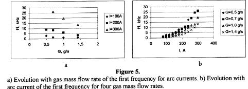
Evolution with gas mass flow rate of the first frequency for and 9.5 kHz for I = 220
A ( G = 0.7 g/s, figure 4 a), 1.5 kHz for I = 100 A and 6.8 kHz for I = 220 A (G = 1.07 g/s,
figure 4 b). Evolution with gas mass flow rate of the first frequency for arc currents are
presented in the figure 5a. Evolution with arc current of the first frequency for four gas mass
flow rates are shown in the figure 5b. Evolution with gas mass flow rate of the second
frequency for arc currents are given in the figure 6a. Evolution with arc current of the second
frequency for four gas mass flow rates are presented in the figure 6b.
It can be seen from figures 4a and 4b that the voltage fluctuations contain a quasi-regular part and small-scale fluctuations. The quasi-regular voltage fluctuations have been
observed before in plasmatrons working with nitrogen [2-5]. Regular voltage fluctuations are
closely connected with the arc interruption by the longitudinal flowing gas. It is a quasi-periodical process. Either the arc is sliding along the expanding anode or the connecting
channel between the arc column and the anode wall is lengthening with a fixed arc root and
when voltage becomes high enough an electrical breakdown occurs and the new arc is started
(the old long arc is changed by to the new short one). Evolution with arc current of the first
frequency for four gas mass flow rates (the figure 5b) is correlated with results [4]. The
amplitudes of the both frequencies for all gas mass flow are decreasing with increasing the
current. The amplitudes of the both frequencies for all measured currents are increasing with
increasing gas mass flow.
|

|

|
As one could to see from figures. 4a and 4b with regular voltage fluctuations a large
band of small amplitude fluctuations exist. Small amplitude fluctuations exist up to the
frequency 50 kHz. Like the regular voltage fluctuations small amplitude fluctuations may be
generated by the arc displacement. The arc is permanently switched on and off producing a
long band noise. These fluctuations may also be generated by the current-convection and\or
the Kelvin-Helmholtz instability [7,8]. Our experimental investigations of the radiation
properties reveal violation of thermodynamic equilibrium conditions in arc plasmas,
especially in nitrogen. It is obvious that correlation between voltage and temperature
fluctuations exists. Such correlation has been studied in [9] in a plasmatron with a cylindrical
channel. It is however difficult to say if small amplitude voltage fluctuations in the arc are
caused by the flow turbulence or if the flow turbulence are caused by the electric fluctuations
and the real nature of these small-scale fluctuations is still unknown. Our results obtained in a
cylindrical channel demonstrate the difference in the spectra of fluctuations in cylindrical and
conical channels.

| 3. CONCLUSION
It is obvious that strong fluctuations of the voltage demonstrate us the existence
several kinds of non-steady processes in plasmatrons with a conical expansion channel. Using
a Fast Fourier Transform influence of working parameters on spectra of voltage fluctuations
in nitrogen plasmas were measured. Evolution with arc current and gas mass flow rates
frequencies and their amplitudes were investigated. Analysis of the fluctuation structures may
show the sources of fluctuations and give the flow stability criterion [7,8] that are so
important for technological industrial applications.
|
REFERENCES
- Isakaev E.Kh., The generalized voltage-current characteristic of the electric arc in
the plasmatron with the longitudinal gas flow, Preprint # 2-380, 1994, Science and
Technological Center, Inst. for High Temperature, Russian Academia of Science (in Russian).
- Dooley M.T., McGregor W.K., and Brewer L.E., Characteristics of the arc in a
Gerdien-type plasma generator, ARS J , Vol. 32, 1962, pp. 1392-1394.
Wutzke S.A., Pfender E, Eckert E.R.G., Investigation of the electric arc in the gas
flow. AIAA Journal, Vol. 5, No 4, 1967, pp. 123 132.
- Fauchais P., Coudert J.F., Vardelle M., Transient phenomena in plasma torches and
in plasma sprayed coating generation. J. Phys. in France (Colloque C4, Supplement au Journal
de Physique III d'octobre 1997), Vol.7, 1997, pp. C4187-198.
- Dautov G.Yu., Dzuba B.A., Karp I.N., Plasmatrons with stabilised arcs, Naukova
Dumka, Kiev, 1984 (in Russian).
- Bendat J.S., Piersol A.G., Engineering applications of correlation and spectral
analysis, Jonh Wiley & Sons, New York-Chichester-Brisbane-Toronto, 1980.
- Sinkevich O.A., Some new physical aspects of the strong electric current
commutation, Sbornik Vysokeho Uceni Technickeho v Brne, No 2-4, 1992, pp. 131-158.
- Artemov V.I., Levitan Yu.S., Sinkevich O.A., Instabilities and turbulence in low-
temperature plasmas Moscow Power Engineering Publishing House, Moscow, 1994 (in
Russian).
- Hlina J., Slechta J., Temperature measurements in an oscillating plasma jet, 11th
Symp. On elementary processes and chemical reactions in low temperature plasma, Book of
contributed papers, Part I, Low Tateras, 1998, pp. 79-82.
INVESTIGATION
OF A THERMAL PLASMA FLOW IN PLASMOTRON WITH MODULATION OF ARC CURRENT
Farih A. Salyanov
Institute of Mechanical Engineering RAS, 2/ 31 Lobachevsky Str., PO Box 99, 420503 Kazan, Russia
Fax 007(8432) 365289, E - mail: Salyanov @ sci. kcn. ru
EXTENDED ABSTRACT
In this paper the general solution of the nonstationary boundary value problem
of the thermal plasma flow in plasmotron is presented. The set of equations allows for
the processes Joul's dissipation of energy, heat conduction, convective heat transfer
and heat transfer by radiation. Unlike the well-known nonstationary theories, our
mathematical model allows for axial acceleration of the plasma flow, axial change of
electric current in the plasmotron and change the radius of the arc column.
As follows from the our theory, modulation of the arc current leads to the
existence of the longitudinal waves of temperature and electric conductivity of the
thermal plasma, electric field strength and other characteristics of the plasmotron and
plasma flow. From the presented theory it can be seen, that the plasma flow in the
plasmotron with the modulation of the arc current has the internal inductance
distributed along the channel.
Processes of heat and mass transfer in the area of arc column can be described by
the following combination of equations:
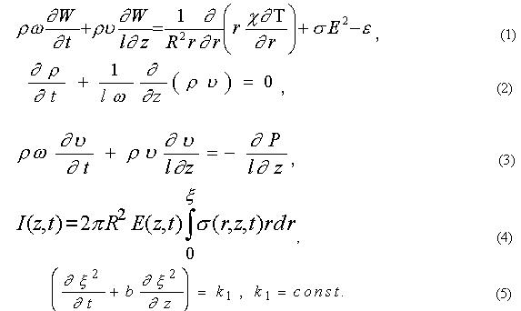
The law conservation the radius of the positive arc column (eq.5) it has been
introduced for the fist time. Here the following notation is used: r, z are the cylindrical
coordinates referred to R and l, respectively; R, l are the channel radius and its length;
t is the time multiplied by w; r, u, c, W , s, e, P , density, axial component of velocity,
heat conduction, total energy per unit mass, electric conductivity, emissivity, and the
gas pressure; w is the frequency of oscillation; I is the current; E is the electric field
intensity; x=x1/R, x1 -radius of the arc column.
Let us take advantage of the Riman method and assume that for the
thermodynamic processes in the arc column in the form polytropic equation, from the
equation (2) (3) we have [1]

Analysing equations (6), one can see that the condition u=const implies that
the process is isothermal or isobaric, the theoretical condition ru=const assumes the
condition r=const . Thus, when modeling the thermal plasma flows in plasmotrons, it
is necessary to take into account the axial acceleration of the plasma flow and the
variations in the gas expenditure in the channel.
The general solution of the equations (1)(3) we have can be introduced 
Let us assume the linear approximations of the functions N ,r, e depending on the
function S, where S=S1-S*, S* is the value of S1 the function at r=x and
arbitrary initial and boundary conditions in the form:

It is seen that this nonstationary thermal problem takes into account the axial
acceleration of the thermal plasma flow, variability of the expenditure and compressibility of the gas, radius of the arc column and the arc current in the channel of the
plasmotron.
The solution of this problem to get to take advantage the modification method of
the D'Alamber. For the function we have the expression

The functions  , may be obtained from (9) and initial and boundary
conditions (8), for example we have
, may be obtained from (9) and initial and boundary
conditions (8), for example we have  ,
where t can be obtain from the equation ,
where t can be obtain from the equation
 , ,  , ,  (10) (10)
Fn - degenerated hypergeometrical functions [2]. The functions An(t) is obtained
from An(t) , An(t) - Fourier coefficients of the expansion Fn of the j1(r,t) , with in
the interval  . .
The general solution of equation for the function E (z,t) we have in the form

This formulas to allow is studies in detail the influence of the modulation
parameters, physics properties and expenditure of the gas flow, geometrical forms the
channel on the characteristics of the arc column and the plasma flow.
From the presented theory can be see, that the reactive component of the
impedance the nonstationary arc column are depend on the amplitude oscillation of the
electricity current, property and expenditure of gas and geometrical form of the
channel. For the first time ascertained that the thermal plasma flow in the plasmotron
with the modulation of the arc current to have the distributed along the channel of the
internal inductance.
REFERENCES
- Salyanov F. A. Influence of arc current modulation on thermal plasma flow in
plasma torches. "Thermal Plasma Torchers and Technologies" Ed. O. P. Solonenko,-
Cambridge, Int. Sci.Publ., England, 1999, v.1.
- Salyanov F. A., Sharapov M. M. Theory of the arc column the nonstationary arc
current in the channel with the gas flow. - Engineering Physical Journal, 1982, T.XLII,
N 4, p. 648 - 652, (Minsk, In Russian).
- Salyanov F. A. Basis of physics of low temperature plasma, plasma apparatus and
technologies. - Moscow: Nauka, Physmatlit, 1997. - 240 p. (In Russian).
REVERSE VORTEX FLOW STABILISED ICP
Alexander Gutsol*, Jussi Larjo** and Rolf Hernberg**
*Institute of Chemistry and Technology of Rare Elements and Mineral Raw Materials, Kola Science Centre of the Russian Academy of Sciences
Fersman St., 14, Apatity, Murmansk Reg., 184200, Russia (visiting scholar in **)
**Tampere University of Technology, Plasma Technology Laboratory ,
P.O. Box 692, FIN-33101 Tampere, Finland
This paper presents first experimental results on the application of reverse vortex flow in radio-
frequency (RF) inductively coupled plasma (ICP). This technique has been used previously in
microwave (MW) plasma torch1-3 and a gas burner using this principle has been described4.
The vortex method of plasma and flame stabilisation is well known. In this method the swirl
generator is placed upstream relative to the electric discharge or flame and the outlet of the hot
gaseous jet is directed to the opposite side. It is well known that in an intensive vortex stream a
central recirculation zone of reverse flow occurs near the swirl generator. The recirculation flow
results in an upstream transfer of energy from the centre of the vortex stabilised plasma or flame. The
hot reverse flow mixes with the incoming cold direct vortex flow. In gas burners this mixing
results in ignition of new gas portions and high intensity and stability of the flame. After mixing the
direct vortex of hot mix moves along walls of the plasma torch or gas burner, and a significant part
of thermal energy arrives at the device walls and becomes lost. This well-known phenomenon
demands sufficient cooling of the device walls.
According to the new concept for insulation of high temperature and reacting zones1 based on the
idea of reverse vortex formation, the outlet of the plasma or flame jet is directed to the swirl
generator side. In this case cold gas should enter the hot central zone from all sides except the outlet
side, and no significant recirculation zone should be formed. During motion near the device walls the
cold gas cools them, so the energy previously absorbed by the walls from radiation, for example, is
recuperated. Portions of the gas changes direction of their motion from the swirl-axial to radial-axial
because of deceleration dye to viscosity and because of heat expansion. These radial-swirl moving
gas portion compress the central hot zone, so the heat flux from the hot zone to the walls became be
lower. Such simple changing the location of the vortex inlet to the exit end of the MW plasma torch1-
3 leads to a significant decrease of the heat loss to the wall: from 30% to 5%.
The scheme of the RF inductive plasma torch with the reverse vortex flow is shown on Fig. 1.
Plasma gas enters the discharge volume through tangential swirler 2. The water-cooled nozzle 1
prevents immediate exit of the plasma gas from the volume. On the left side of the scheme the gas
stream lines 5 are shown. The stream lines 7 of the gas and plasma in the radial plane are shown on
the right side of the Fig 1. The discharge volume is restricted by the quartz tube 3. Water-cooled
inductive coil 4 supplies RF electromagnetic energy which is absorbed in the toroidal skin-layer 8 of
the plasma fluid 9. Plasma leaves the discharge volume as a jet 6 through the nozzle 1.
 There is one fundamental difference between the previously investigated environments and ICP. In
MW plasma and combustion flame there is a central hot zone with low flow velocity that acts as a
stabilising core producing active species and electrons. In ICP, the RF field energy is absorbed in a
toroidal zone 8 around the centre. The diameter of this zone determines the coupling efficiency of
the energy transfer from the inductive coil 4 to the plasma 9. In reverse vortex flow, there is a
significant negative radial flow component
over the whole length of the active region.
This radial flow should compress the
toroidal skin-layer zone 8. Therefore, the
stability of this setup should be lower than in
MW or flame.
There is one fundamental difference between the previously investigated environments and ICP. In
MW plasma and combustion flame there is a central hot zone with low flow velocity that acts as a
stabilising core producing active species and electrons. In ICP, the RF field energy is absorbed in a
toroidal zone 8 around the centre. The diameter of this zone determines the coupling efficiency of
the energy transfer from the inductive coil 4 to the plasma 9. In reverse vortex flow, there is a
significant negative radial flow component
over the whole length of the active region.
This radial flow should compress the
toroidal skin-layer zone 8. Therefore, the
stability of this setup should be lower than in
MW or flame.
Our experiments show that it is possible to
obtain stable ICP plasma with reverse
vortex flow configuration. The experiments
were accomplished using a common RF
plasma torch with a frequency of 2 MHz.
The quartz plasma chamber has inner
diameter of 75 mm. The 4-loop inductive
coil has inner diameter of 90 mm and length
of 100 mm. The distance between the 50
mm nozzle and the inductive coil is 70 mm.
We have used argon as a plasma gas. In
some experiments the admixture of nitrogen
was used.
Visually it was possible to distinguish 6
different regimes of plasma generation.
- Pressure P~10 kPa, plate power W=9.5 kW, argon consumption QAr = 0.45 -
0.65 g/s. The discharge has unusual shape
like a drop or a mushroom (upside-down).
The "thick" pink part of such discharge is
inside the inductive coil and the diameter of
this part may be as large as inner diameter of
the quartz chamber. The "thin" yellow part
(plasma jet) is extends up to the nozzle and
has a diameter of about 40 mm.
- P~35 kPa, W = 25 kW, QAr = 0.75 g/s. Very interesting regime with very high value of specific
power W/Q. The bright white zone of this discharge has conical form with the bottom of diameter 57
mm on the level of the lower loop of the inductive coil. The narrow top of diameter 20 mm was
directed to the nozzle. The pink zone was around this white cone, and diameter of this zone was
about 45 mm near the nozzle.
- P~50 kPa, W = 8 - 9 kW, QAr = 0.5 g/s. Unstable form. The discharge is cigar-shaped with a
small maximum diameter of 42 mm inside the inductive coil.
- P~50 kPa, W = 9.5 - 13 kW, QAr = 0.8 - 1.2 g/s. The form of this discharge is a combination of
two cones. The narrow part of the upper cone is near the nozzle and has diameter of about 50 mm
(which corresponds to the nozzle diameter). The top of the second cone is a little lower than the
lower loop of the inductive coil. These two cones have the common base with a diameter of 60 - 65
mm close to the middle of the coil.
- P~50 kPa, W = 16 - 22 kW, QAr = 1.3 - 3.3 g/s. A very stable discharge of the barrel form. The
bottom of this "barrel" with diameter of 62 - 70 mm is a little lower than the lower loop of the
inductive coil, the top with diameter of 55 mm touches on the nozzle. It is possible to distinguish the
darker core of the flow near the nozzle.
- Atmospheric pressure discharge, W = 13 - 18.5 kW, QAr³
0.9 g/s. The central downstream flow is
obvious in this case: plasma flows out from the chamber only near the nozzle periphery and a plasma
"tail" extends much lower the inductive coil. We mixed an axial flow with this discharge. The axial
flow was directed upwards from the tube with inner diameter of 4.5 mm at 60 mm down from the
coil. When this axial flow was very weak some instability of the discharge was obvious. But when the
axial flow became stronger the discharge became very stable, and the axial flow gas consumption may
reach the consumption of the tangential flow. With addition of the axial flow the plasma jet flows out
from the chamber near to the axis of the nozzle. It is possible to add some nitrogen into the axial flow
or (with less consumption) into the tangential flow. With addition of nitrogen the diameter of the
discharge was smaller and plate power needed to be increased.
The first obvious advantage of the reverse vortex stabilised ICP is that the gas consumption for stable
operation with the a quartz plasma chamber is lower than with conventional direct vortex flow
stabilisation. The second one is the possibility of stable operation with a strong additional axial flow.
REFERENCES
- Kalinnikov V. T. and Gutsol A. F. A New Efficient Method of Insulating High-Temperature and
Reacting Systems and the Ranque Effect. - Doklady Akademii Nauk, 1997, V. 353 (4), p. 469-
471. (Physics - Doklady, Vol. 42, No. 4, 1997, pp. 179 - 181).
- Gutsol A., Bakken J. A. New Vortex Method of Plasma Insulation, 13th Symposium on Plasma
Chemistry - ISPC-13, Beijing, China, Aug.18-22, 1997. Symp. Proc., Beijing, Vol. 1, p. 155-160.
- Gutsol A., Bakken J. A. New Vortex Method of Plasma Insulation and Explanation of the Ranque
Effect.- J. Physics D: Applied Physics , 1998 , V. 31, No. 6, pp. 704 - 711.
- Kalinnikov V. T. and Gutsol A. F. Insulation of the gas flame in the reverse vortex. - Doklady
Akademii Nauk (Physics - Doklady), 1998, V. 360 (1), p. 49-52.
EFFECT OF VORTEX MOTION OF STABILIZING LIQUID WALL ON PROPERTIES OF ARC IN WATER PLASMA TORCH
J. Jenista, V. Kopecky, M. Hrabovsky
Institute of Plasma Physics AS CR, Za Slovankou 3, 182 21 Praha 8, Czech Republic
INTRODUCTION
In water stabilized plasma torches an electric arc is ignited in a centre of water vortex which is created in cylindrical arc chamber with tangential water injection. The arc is stabilized by an interaction with inner wall of the vortex. Principle physical mechanisms which control arc properties and parameters of generated plasma jet are evaporation of water wall and heating and ionization of vapour flowing from the wall into the arc column. The vortex movement of water is necessary to maintain fixed shape of inner wall of the vortex due to inertial forces. Published model of mechanisms of water stabilized arc does not consider effect of movement of water on mechanisms of arc1. The aim of investigation described in this paper is theoretical and experimental study of the effect of movement of water and induced tangential component of velocity of plasma in the arc column on properties of arc and generated plasmajet.
THEORETICAL MODEL
The published numerical model of water stabilized arc2 does not take tangential movement of the discharge into account. It can be expected that a part of rotating momentum of a swirl is transferred to the arc plasma, i.e. the plasma discharge is rotating with nonzero tangential velocity. Thus the two-and-half dimensional axisymmetric model including the arc discharge area between the cathode and the outlet nozzle of the torch has been formulated. The plasma flow is assumed to be steady, laminar, mildly compressible in the state of local thermodynamic equilibrium. Radiation effects are involved through the net emission coefficient; it is assumed that the optical thickness of the arc corresponds to the arc radius (3 mm). Absorption of radiation in water vapours is omitted. Magnetic field is generated only by the arc itself, gravity effects and viscous dissipation are negligible. The mass flow rate of water vapour, i.e. production of plasma material itself, is assumed to be uniform along the discharge and its value is derived from experiments. The complete set of conservation equations describing the mass, electric charge, momentum (three velocity components - axial, radial, tangential) and energy transport of such atmospheric-pressure plasma with temperature-dependent transport and thermodynamic properties is solved numerically by the control volume method of Patankar3.

Distribution of tangential velocity component within the discharge as well as the overall impact on arc characteristics were studied. Calculations were carried out for a broad range of tangential velocities 5 - 150 m/s near the phase transition water - vapour (boundary conditions) for arc currents 300 A - 600 A. According to the simplified expressions of Maecker4, the expected magnitudes of tangential velocity component near the phase transition boundary should be ~5-10 m/s for inlet pressures 0.39 MPa and 0.6 MPa at which the water plasma torch is operated in the experiments.
The numerical results proved that the effect of tangential velocity on arc characteristics, even in this broad interval of velocities, is negligible (the maximum difference in the axial outlet temperature, velocity, electric potential and pressure drop is less than 2 % regarding the case when the tangential velocity is omitted). This is because centrifugal forces appearing in the radial velocity equation are small compared to dominant terms in this equation. Radial profiles of tangential velocity exhibit different shapes for different currents; see Fig. 1. For lower currents, tangential velocity decreases
nearly monotonously from the vapour region to the arc axis within the discharge volume while for higher currents tangential velocity has a maximum close to the arc axis. The peak of tangential velocity becomes more pronounced with increasing current. This behaviour is related to the temperature dependence of the dynamical viscosity. For higher currents, axial temperatures exceed 20 000 K where the degree of ionization is more than 90 % and dynamical viscosity rapidly decreases.
EXPERIMENTS
Experiments were performed with water stabilized plasma torch described in1. The torch was operated at power levels 100-200 kW. As the torch has external anode created by water cooled disc, two axial arc sections can be distinguished. The main part of internal section is cylindrical arc column with length 50 mm which is surrounded by stabilizing water vortex. The part between the torch nozzle and the arc attachment at the anode is composed of arc column in the plasma jet downstream of the nozzle with the length 15-20 mm and the anode attachment region. In the experiments the voltage and the power balance of both sections were measured separately. The flow rate of stabilizing water was varied in the range from 12 to 20 l/min and thus tangential velocity of water in the vortex varied substantially. These changes of water flow rate has no effect on power balance and voltage drop on both arc sections. However, the Fourier analysis of signals of voltage drop on both parts of the arc reveal the characteristic frequency in the range 250 - 450 Hz, which was dependent on water flow rate. The dependence on water flow rate and arc current was measured. The frequency is directly proportional to water flow rate and its value corresponds to frequency of vortex motion of water in stabilizing wall.
CONCLUSIONS
It was numerically proved that rotation of plasma column due to tangential velocity components has negligible effect on the overall arc performance. For higher currents, the tangential velocity component increases near the axis due to low dynamical viscosity of water plasma. The same conclusion can be deduced also from the experiments, where the change of flow rate of water has no effect on measured arc characteristics. The rotation of water induces fluctuations in the arc and in plasma jet with characteristic frequency which is related to the frequency of rotation of water.
ACKNOWLEDGEMENT
Financial support from the Grant Agency of the Czech Republic under projects No. 106/96/K245 and 102/98/0813 is gratefully acknowledged.
REFERENCES
- Hrabovsky M., Konrâd M., Kopecky V., Sember V., Processes and properties of electric arc stabilized by water vortex, IEEE Trans. on Plasma Science 25 (1997), No. 5, 833.
- J. Jenista, Numerical model of a water-swirl stabilized electric arc, in Proc. 12th Int. Conf. on Gas Discharges and Their Applications, Greifswald, Germany (edited by G. Babucke, publisher: Local Organising Committee of GD'97), Sept. 8-12, 1997, vol. 1, pp. 50-53.
- S. V. Patankar, Numerical Heat Transfer and Fluid Flow, McGraw-Hill, New York, 1980.
- H. Maecker, Ein Lichtbogen fur hohe Leistungen, Z. f. Phys. 129 (1951), 108.
DEMIXING IN FREE-BURNING ARCS: A COMPARISON OF
THE PREDICTIONS OF A NUMERICAL MODEL WITH SPECTROSCOPIC MEASUREMENTS
A. B. Murphy
CSIRO Telecommunications and Industrial Physics, P.O. Box 218, Lindfield NSW 2070, Australia
K. Hiraoka
National Research Institute for Metals, 121 Sengen, Tsukuba-shi, Ibaraki 305-0047, Japan
Demixing is a diffusion-driven phenomenon that leads to the partial separation of different chemical
elements present in plasmas. It is an important effect in thermal plasmas in gas mixtures. Many
plasmas used in industrial processes belong to this category. Examples are TIG welding arcs, in
which helium or hydrogen is often added to the argon plasma gas, MIG welding arcs, in which a
mixture of argon and carbon dioxide or oxygen is used, and plasma spraying jets, in which nitrogen,
helium and hydrogen may be added to argon. A number of different physical processes lead to
demixing1-3. The most important are demixing due to partial pressure gradients, which concentrates
the chemical elements with the higher ionisation energies in the high-temperature regions of the
plasma; demixing due to frictional forces and due to thermal diffusion, both of which concentrate
the lighter chemical elements in the high-temperature regions; and cataphoresis, or demixing due to
electric fields, which concentrates the chemical elements with the higher ionisation energies near
the anode. Demixing can lead to large changes in composition (changing the concentration of a
given element by more than a factor three in some cases), and can also significantly alter the flow
velocity and the thermal transport in a plasma1.
A two-dimensional numerical model of demixing in atmospheric-pressure free-burning arcs1, which
incorporates the combined diffusion coefficient treatment of diffusion4, has been developed. In the
model, the coupled partial differential equations describing conservation of mass, energy,
momentum, charge and species are solved using the methods developed by Patankar5. Arcs in
mixtures of argon with helium, nitrogen, oxygen, and hydrogen have been modelled. The
predictions of the model have been compared with spectroscopic measurements of the composition
of argonnitrogen arcs; good agreement was found1.
Recently, Hiraoka has published a number of papers6-9, mainly in the Japanese literature, describing
spectroscopic measurements of composition and temperature of free-burning arcs in mixtures of
argon with helium and hydrogen. This has provided the opportunity for a further comparison of the
predictions of the numerical model with experiments. Results of this comparison will be presented
and discussed in this paper.
All spectroscopic measurements were performed on a 5 mm long free-burning arc between a
3.2 mm diameter, 45° included angle thoriated tungsten cathode and a water-cooled copper anode.
The arc current was 100 A, and the total gas flow was 10 L min-1. An optical lens system was
mounted on an xz stage which was scanned across the arc using stepper motors. An optical fibre
was used to transmit the light to a 0.25 m monochromator and a photomultiplier. Line-averaged
intensities were converted to radial profiles using an Abel inversion.
Measurements6-8 of composition and temperature in argonhelium arcs were performed by
measuring the relative intensity of the 696.5 nm Ar I line and the 480.6 nm Ar II line emitted by the
arc. Measurements of the 587.6 nm He I line were also performed to confirm the existence of local
thermodynamic equilibrium (LTE). It was found that for helium mass fractions above around 0.15,
LTE could no longer be assumed, and measurements became unreliable. Results of measurements
of helium mass fraction on axis, 1 mm below the cathode, are shown in Figure 1. Also shown are
mass spectroscopic measurements, performed by sampling the gas through a small hole in the anode
in a 1 mm long arc. Good agreement is found between the results obtained by the two techniques,
despite the change in arc length. A strong increase in the helium concentration near the arc axis is
observed, with the mass fraction of helium doubling compared to the value in the input gas mixture.

|
Calculations of helium mass fraction performed using the numerical model for the conditions of the
optical spectroscopic measurements are also shown in Figure 1. Excellent agreement is found
between the calculations and the measurements.
Spectroscopic measurements of the composition and temperature of arcs in mixtures of argon and
hydrogen were performed by two methods. The first6,8 was the same method used for the argonhelium arcs, requiring measurements of an ArI line at 696.5 nm and the ArII line at 480.6 nm. The
second8-9 required measurements of the 696.5 nm ArI line and the 656.2 nm HI line (the Ha line).
Results obtained by both methods for an arc containing 10% hydrogen by mole (0.56% by mass)
are compared in Figure 2 with the predictions of the numerical model.
Similar results are obtained by the two spectroscopic methods. They show that the hydrogen mass
fraction reaches around 0.025 at z = 1 mm (a factor of 4.5 increase on the input mass fraction of
0.0056), indicating that demixing strongly concentrates hydrogen in the high temperature region
near the axis. Temperatures in this region are measured to be around 16500 K by the ArI ArII
method, and around 15500 K by the ArI Ha method.
The numerical model predicts a similar trend to that found in the measurements, but the calculated
hydrogen mass fraction on axis at z = 1 mm is about 0.013, significantly smaller than the measured
value. At z = 2 mm, the predictions of the model agree much more closely with the measurements.
The predicted temperature at z = 1 mm is 15800 K, which also agrees well with the measurements
It is possible that departures from LTE, which are often observed in free-burning arcs close to the
cathode10, may lead to errors in the spectroscopic measurements at z = 1 mm in the argonhydrogen
arc. Apart from this case, good agreement is found between the predictions of the model and the
spectroscopic measurements.
| |
Figure 1. Helium mass fraction on axis, 1 mm below the cathode, plotted against the mass fraction
of helium in the input gas mixture. Measurements performed using optical spectroscopy for a 5 mm
long arc are compared with the predictions of the numerical model. The solid line shows
measurements made using mass spectroscopy in a 1 mm long arc, and the dotted line represents the
hypothetical case of no demixing.
.
|

|
|
Figure 2: Radial dependence of the hydrogen mass fraction 1 mm and 2 mm below the cathode in
an arc in 10% hydrogen and 90% argon by mole. Measurements made using two optical spec-
troscopy techniques are compared with the predictions of the numerical model. The input compo-
sition (which would be maintained if there were no demixing) is shown for reference.
|
REFERENCES
- Murphy, A. B., Demixing in free-burning arcs, Phys. Rev. E, Vol. 55, No. 5, pp. 7473-7494,
1997.
- Frie, W., Entmischungseffekte bei Gemischen ionisierender Atomgase, Z. Phys., Vol. 172, pp.
99-117, 1963 (in German).
- Murphy, A. B., Cataphoresis in electric arcs, J. Phys. D: Appl. Phys., Vol. 31, No. 23, pp. 3383-3390.
- Murphy, A. B, Diffusion in equilibrium mixtures of ionized gases, Phys. Rev. E., Vol. 48, No.
5, pp. 3594-3604, 1993.
- Patankar, S. V., Numerical Heat Transfer and Fluid Flow, McGraw-Hill, Washington DC, 1980.
- Hiraoka, K., Evaluation of local plasma composition and temperature in mixed gas tungsten arc
plasma column by light spectroscopy Study on characteristics of gas tungsten arc shielded by
mixed gases (Report 2), Quart. J. Japan Weld. Soc., Vol. 11, No. 1, pp. 68-74, 1993 (in
Japanese).
- Hiraoka, K., Dr.Eng. Thesis, Osaka University, 1996 (in Japanese).
- Hiraoka, K., Plasma structures of ArH2 mixed gas tungsten arcs determined by spectroscopic
measurements, Welding International, Vol. 12, No. 3, pp. 186-194, 1998 (translated from Quart.
J. Japan Weld. Soc., Vol. 15, No. 2, pp. 259-266, 1997).
- Hiraoka, K., Demixing in argonhelium mixed gas tungsten welding arcs, Proceedings of the
11th International Symposium on Plasma Chemistry, Loughborough, U.K., 1993, Vol. 1, pp.
440-445.
- Haidar, J., Non-equilibrium modelling of transferred arcs, J. Phys. D: Appl. Phys., Vol. 32, No.
3, pp. 263-272, 1999.
MODELLING OF HEAT AND MASS TRANSFER PHENOMENA DURING PLASMA ENHANCED ELECTROWINNING PROCESS
William Haskins*, Jerzy Jurewicz**, Patrick Taylor*
*Plasma Processing Laboratory,
Metallurgical & Mining Engineering, University of Idaho, USA,
**CRTP, Plasma Technology Research Centre,
Chemical Engineering Department, Université de Sherbrooke, Québec, Canada
ABSTRACT
The transferred arc DC plasma furnace, operating under reverse polarity, allows enhancement of
the process of oxide reduction by combining the thermal and chemical effects of plasma with the
electrochemical reduction of the metal at the cathode - molten bath interface. The modeling of the
heat and mass transfer phenomena observed during such plasma enhanced electrochemical
processes is an objective of this study.
The analyzed setup, composed of a transferred arc plasma torch working as an anode and a
molybdenum cathode inside a bath of molten oxides, was characterized by the presence of several
interfaces. For the simplicity of modeling only two principal ones are considered in this paper -the
molten metal/molten bath interface and the molten bath/plasma interface. The reduction system
analyzed was chromium- chromium (III) oxide with the addition of barium oxide to lower the
melting point of the reacting mixture. The controlled concentration of the carbon monoxide in an
argon - nitrogen plasma was necessary to scavenge oxygen atoms generated during the
electrolysis process. The reactions considered were :

The barium oxide present was considered electrochemically inactive but its concentration
(activity) was important as a potential charge carrier. Both the oxygen ion concentration
distribution through the depth of molten bath and superimposed on it the electric field were
considered as the principal driving forces. The discussed process temperatures were between
1800 - 2300oC . The heat and mass transfer model and the actual experimental results[1] are
compared .
[1]Haskins W., J.Jurewicz, P.Taylor, "Plasma Enhanced Electrowinning of Metals from
Oxides", paper to be published at the International Symposium on Plasma Chemistry to be held at
Prague, Czech Republic on August the 2-6, 1999,
TRANSPORT PROPERTIES OF IONIZED SPECIES
Stefan Selle, Uwe Riedel
Interdisziplinäres Zentrum für Wissenschaftliches Rechnen
Universität Heidelberg, Im Neuenheimer Feld 368, D-69120 Heidelberg, Germany
The knowledge of the transport properties of ionized species is an essential pre-requisite for the
numerical simulation of many industrial applications using plasma. The main objective of this paper is
to develop a transport model which can be used in a number of these applications, e.g. in plasma etch
reactors for semiconductor manufacturing, for the prediction of heat load of re-entry vehicles, or in
internal combustion engines during spark ignition. The applications differ in plasma composition,
temperature and pressure range. This work presents a universally applicable transport model of
ionized flows which uses little input data and consumes moderate computational resources without
sacrificing accuracy. It focuses on air plasma since a comparison can be made with results published
in the literature.
The transport model is based on the theory of dilute gases of Chapman and Enskog (CE) with an
extension to polyatomic gases: the modified Eucken correction. Binary transport coefficients are
calculated from collision integrals which can be interpreted as the mean collision cross sections of the
interaction between two particles. Different particle interactions are described by various
intermolecular potential functions: Stockmayer-(12-6-3) potential, exponential repulsive potential,
(16-6-4) potential, and Debye-Hückel potential.
Therefore, the following molecular input data is required: Lennard-Jones parameters, Born-Mayer
parameters, dipole moments, dipole and quadrupole polarizabilities, and dispersion energies.
Combination rules are used to get the potential parameters of the interaction between different
species. Resonant charge transfer is modeled by a simple approximation of collision cross sections.
Altogether, the transport model only needs 8 input values for each neutral and 4 input values for
each charged species to get the full set of collision integrals. Only the collision integrals of electron-
neutral interaction must be calculated by numerical integration from collision cross section data. This
approach is very flexible due to the fact that the tedious task of evaluating the n(n-1)/2 collision
integrals of an n-species mixture is avoided.
Ordinary diffusion and thermal diffusion coefficients, viscosity, thermal and electrical conductivities
in a multicomponent mixture are calculated in first order CE-theory from binary transport properties.
Electron thermal conductivity coefficients are calculated in a third order approximation using
simplified expressions. Ambipolar diffusion effects are considered. Conjugate gradient methods and
simple mixture rules are compared (see below).
The transport properties of an 11-species air model (N2, O2, NO, N, O, N2+, O2+, NO+, N+, O+, and e-) are calculated for pressures at 10-4, 1, and 100 atmospheres in the temperature range from 300 to
30000 K. The equilibrium composition of dissociated and ionized air is calculated as the steady-state
of a rate equation model (perfectly stirred reactor) which consists of 26 elementary reactions. The
forward reaction rate coefficients are given in an Arrhenius form and the reverse reaction rate
coefficients are calculated from thermodynamic data.
The binary diffusion coefficients computed are consistent with the quantum mechanical calculations
of Levin et al.1 and the results of Capitelli et al.2, but differ from the calculation of Yos 3.
At atmospheric pressure, the viscosity of the air mixture shows the same temperature behaviour as
the calculations of Gupta et al.4, but the order of magnitude of the maximum differs and depends
strongly on the Born-Mayer parameters of the N-N interaction 5-7 (see Fig. 1).
The total thermal conductivity in a mixture contains contributions of translational and internal
(rotational, vibrational, and electronic excitations) energies and chemical reactions which can be
understood as (ambipolar) diffusion processes of heat enthalpies. At atmospheric pressure and low
temperatures (T < 12000 K) the total thermal conductivity of the dissociated and ionized air is in
good agreement with the results from Gupta et al.4 At higher temperatures the translational
contribution of electrons is dominant and total thermal conductivity is higher than the values
calculated by Gupta et al. (see Fig. 2). For the electrical conductivity only minor differences are
found compared to the results of Yos 3 and Devoto 8 at temperatures below 20000 K.
The calculations on the basis of the simple mixture rules which are about two times faster than the
multicomponent transport formulas, differ only slightly in the temperature range below 12000 K.
Therefore, in the pressure range investigated it is possible to use the simple formulas for
temperatures below 12000 K and to switch to the full multicomponent transport coefficients
computed with conjugate gradient methods above 12000 K.
To summarize, the transport model presented is well suited to be implemented in CFD simulations of
hypersonic re-entry flow fields, where the cpu time needed to compute transport quantities is an
important issue in parametric studies. Furthermore, our approach can be extended to other systems
where plasma-generated ions are important, e.g. plasma etch systems or internal combustion engines.
FIGURES
 
REFERENCES
- Levin, E., Partridge, H., and Stallcop, J.R., Collision Integrals and High Temperature Transport
Properties for N-N, O-O, and N-O, J. Thermophys. 4 (1990) 469, Transport Cross Sections and
Collision Integrals for N(4S0)-O+(4S0) and N+(3P)-O(3P) Interactions, Chem. Phys. Lett. 184
(1991) 505, Resonance Charge Transfer, Transport Cross Sections, and Collision Integrals for
N+(3P)-N(4S0) and O+(4S0)-O(3P) Interactions, J. Chem. Phys. 95 (1991) 6429
- Capitelli, M., Gorse, C., Longo, S., and Giordano, D., Transport Properties of High Temperature
Air, AIAA 98-2936, 7th AIAA/ASME Joint Thermophysics and Heat Transfer Conference, June
15-18, 1998, Albuquerque (NM).
- Yos, J.M., Transport Properties of Nitrogen, Hydrogen Oxygen, and Air to 30000 K, RAD-TM-
63-7, 1963, Research and Advanced Development Division AVCO Corporation, Wilmington
(MA).
- Gupta, R.N., Lee, K.-P., Thompson, R.A., and Yos, J.M., Calculations and Curve Fits of
Thermodynamic and Transport Properties for Equilibrium Air to 30000 K, NASA-RP-1260,
1991, NASA Langley Research Center, Hampton (VA).
- Yun, K.S. and Mason, E.A., Collision Integrals for the Transport Properties of Dissociating Air at
High Temperatures, Physics of Fluids 5 (1962) 380.
- Capitelli, M. and Devoto, R.S., Transport Coefficients of High-Temperature Nitrogen, Physics of
Fluids 16 (1973) 1835.
- Cubley, S.J. and Mason, E.A., Atom-Molecule and Molecule-Molecule Potentials and Transport
Collision Integrals for High-Temperature Air Species, Physics of Fluids 18 (1975) 1109.
- Devoto, R.S., Electron Transport Properties in High-Temperature Air, Physics of Fluids 19
(1976) 22.
PARTICLE TURBULENT DISPERSION IN AN INDUCTIVELY COUPLED RADIO FREQUENCY PLASMA REACTOR
R. Ye, P. Proulx and M.I. Boulos Plasma Technology Research center, (CRTP)
Faculty of engineering, Department of Chemical Engineering Universite de Sherbrooke, QC J1K 2R1 CANADA
The particle-plasma interaction effects in an inductively coupled radio frequency (rf) plasma reactor were investigated. The particulate phase was treated as discrete entities and a particle-source-in-cell (PSI-Cell) approach was employed to track the particle trajectories in turbulent rf plasma flows. The particle temperature and velocity histories for a typical size of 50 mm alumina and tungsten particles are given. The effects of particle turbulent dispersion based on the instantaneous plasma velocity do not show signifýcant difference from the results obtained from the particle dispersion based on the mean plasma velocity. It was found that, in such kind of confýguration and flow conditions, the particles and plasma have strong coupling effects. These effects could vary with the source terms due to the particles that considered, as well as the materials property of the particles. Especially, a signifýcant fraction of energy, more than one-quarter the total energy dissipated in the plasma, could be absorbed by the particles.
PLASMA CONCENTRATIONS OUT OF EQUILIBRIUM :
N2 (KINETIC METHOD AND MASS ACTION LAW), Ar-CCl4 AND Ar-H2-CCl4 (MASS ACTION LAW)
P. Andre*, J. Aubreton**, M.F. Elchinger**, P. Fauchais**, A. Lefort*
* LAEPT, CNRS URA 828, Universite Blaise Pascal, 24, Avenue des Landais, 631 17 Aubiere cedex, France:
** SPCTS, CNRS UMR 6638, Universite de Limoges, 123, Avenue Albert Thomas, 87060 Limoges cedex, France.
I. INTRODUCTION
The calculation of non thermal equilibrium composition may be done through kinetic methods [1-2] or by multi-temperature mass action law (equivalent to Gibbs free energy minimisation) [3]. Theoretically, the fýrst method leads to results of composition more realistic. However, the second way is easier, the knowledge of reaction rates which may be very numerous for a complex chemical system, is not necessary. In these types of plasmas, several temperatures can be defýned : translationals (electrons Ttre ; heavy species Ttrh), rotational (Tr), vibrational (Tv), excitation (Tex). Firstly, we compare the results of compositions calculated, for a nitrogen plasma, by using these two methods. Then the Gibbs free energy minimization is used to determine the composition of a complex chemical system : Ar-CCl4 and Ar-H2-CCl4.
II. COMPOSITION OF NON-EQUILIBRIUM NITROGEN PLASMA
Concerning temperatures, the following assumptions have been made :

Therefore, the plasma has three temperatures and the parameters qe and qv characterize the thermal desequilibrium.
II.l. Chemical kinetic
If the general chemical reaction 1 is considered :

where N is the number of chemical species present in the mixture, Ai represents the chemical species, nfil represents the stoechiometric coefficient corresponding to Ai , in the forward reaction and nfrl in the reverse reaction.
For the 1st reaction, the reaction rate in the forward direction is given by :

where ni is the concentration of ith species, kf1 is the rate coefficient in the forward direction, kr1 is the rate coefficient in the reverse direction for the 1th reaction and x1 is a parameter which measures the progress of the reaction in the forward direction.
These coeffIcients depend on their reaction temperatures (Te or Th). We must note that the rate coefficients kf1 and kr1 are poorly determined. At the chemical equilibrium, the reaction 1 is equilibrated between forward reaction and reverse reaction, then :
 and, it comes :

In plasmas out of thermal equilibrium, the composition calculation method proposed by Richley and Tuma [1] consists in choosing the temperature at which of rate coefficients kf1 and kr1 are calculated and solve the relationship (2). Since the electron velocity is much greater than that of molecules or ions, when an electron is present in the reaction the authors chose the electron temperature as reaction temperature.
However the ratio R = kf1/kr1 should be be the same for a given reaction which is not necessarily the case. For example the nitrogen dissociation may be written

where M is, for example, N or e. When this third species is N or e, the ratio R is modified. Consequently, this system cannot be solved with the temperature as defined by Richley and Tuma. So, two solutions may be used, the first one is to choose the reactions which are the most important at a given temperature, the second is to choose different temperatures.
In our application 5 species and 13 reactions were taken, into account. Results of numerical calculations will be presented and discussed for two values of qe (1.5 and 2) and qv = qe.
II.2. Concentration obtained with a multi-temperature mass action law
The mass action law in a multi-temperature plasma is written [3] :

where vi1 = vfi1-vfr1 , ei0 is the enthalpy of formation, R is the molar gas constant, h is the Planck's constant. Finally, Zri, Zvi, Zexi are successively the rotation, vibration, excitation partition functions of ith species which are caleulated by a new method [4].
Results are obtained in the same conditions as for the kinetic method.
II.3. Conclusion
The results obtained by the three methods (kinetic, pseudo-kinetic and multi-temperature equilibrium) are similar for low desequilibrium constants (qe < 1.5). Thus fýnally we have used the multi-temperature mass action law to calculate the composition of more complex chemical systems.
III. COMPOSITION OF NON-EQUILIBRIiTM COMPLEX CHEMICAL SYSTEM
The multi-temperature mass action law may be written as in section II.2. Moreover, the determination of polyatomic partition function has been done by a method similar to that used by JANAF (harmonic oscillator assumption). However a correction has been introduced for hindered internal rotation for molecules such as for example C2H6.
We have performed the calculations for Ar-CCl4 system (taking into account 22 species) and Ar-H2-CCl4 system (47 species). Our results show that when Tv increases from Ttrh to 2*Ttrh, the concentrations of polyatomic molecules (such as C2Cl6) increase also. That is due to the fact that the vibration free degree are numerous for this type of molecule : 18 degrees of vibration for C2C16 for example.
IV. CONCLUSION
It has been shown, in the case of a nitrogen plasma, that the determination of the composition by the multi-temperature mass action law may be a realistic approximation provided the desequilibrium qe = Te/Th and qv = Tv/Th are below 2. Then we have extended this method to calculate the concentration of more complex chemical systems such as Ar-CCl4 and Ar-H2CCl4.
REFERENCES
- E. Richley and D.T. Tuma, J. Appl. Phys., 3(12)(1982)8537-8341.
- C. Park, « Non equilibrium hypersonic aerothermodynamics », John Wiley and Sons, inc., 1990.
- P. Andre , « Study of the composition and thermodynamics properties of thermal plasmas at equilibrium or out of equilibrium », University of Clermont-Ferrand; F (1995).
- J. Aubreton, M.F. Elchinger, P. Fauchais,. « New method to calculate thermodynamic and transport properties of a multi-temperature plasma : application to N2 plasma », Plasma Chemistry and Plasma Processing, 18, 1(1998) 1-28.
MEASUREMENTS OF HEAT FLUX IN ATMOSPHERE AND TEMPERATURE CONTROL PLASMA SPRAYING PROCESS
Erick Meillot, Jean Pierre Fromentin
Commissariat â L'Energie Atomique,
Le Ripault, B.P. 16, 37260 MONTS, FRANCE, meillot@ripault.cea.fr
Coatings with oxygen sensitive particles by plasma spraying on thermal sensitive substrates need a special process :
- first, the atmosphere must be free with oxygen and must be controlled on line during the spraying,
- second, the overall surface temperature must be kept in a critical range to avoid the destroy of the substrate.
So, the C.E.A. (the Freneh Atomic Energy Agency) haa developed the A.T.C. process {Atmosphere and Temperature Control) : a classical inert plasma spraying system and a liquified gas atomization are coupled together :
- the first one builds the coating
- the second one cools down the substrate after the previous one.
This process supplies alternately positive and negative heat fluxes to the substrate. In order to quantify theses fluxes, and to have a better control of the process, a heat flux measurement diagnostic has been developed : with industrial conditions, several multi-layer sensors measure the flux received by the substrate. Of course, the powder is not introduced in the plasma jet because it would destroy the apparatus.
This paper presents the diagnostic apparatus and the first results measured in A.T.C. plasma spraying conditions. These results are obtained in dynamic experiments.
Diagnostic apparatus:
The apparatus is a copper sheet with eleven multi-layer sensors (1O mm x 10 mm x 10 mm) stuck on it at different positions {figure 1) and connected to an acquisition data computer. Three thermocouples measure the surface temperature of the copper sheet. A varnish protects the probes but the measurement can be done only in the end of the plasma plume.

Experimental conditions
The plasma torch is loaded on a robot arm with two atomizers, one on each side of the torch. The robot arm moves in front of the flux measurement apparatus (îrom left to right, at the middle position of the sensors 5, 10 and 11 on the figure 1) : each sensor receives a signal directly proportional to the heat (negative signal for cooling flux, and positive one for heat flux).
For the experiment tests, the SPRAYING SYSTEM atomizer is twin-fluid atomizer. The liquid is liquefied argon at 0.24 MPa pressure and the assistance gas is still argon at 45 sm3h flow rate.
The plasma torch supplies 13.5 kW with ternary gas mixture (Argon/Helium/Hydrogen). The distance between the torch exit and the substrate is about 150 mm and the distance between the substrate and the atomizers is about l00 mm. The moving velocity of the robot arm in front of the apparatus is about 1000 mm/s.
First results
The figure 2 shows the heat fluxes recorded by the three centered sensors (Sensors referenced S5, S10 and S11 ) versus time.

The first peak depends of the cooling flux of the first atomizer, the middle point near the x axis is due to the plasma gas flux, and the last peak is the cooling flux of the second atomizer.
When the first droplets arrive on the copper sheet, they create an important cooling flux during a small time, so the slope of the signal is very straight.
After that, the atomizer moves out and the plasma torch supplies the gas energy to the substrate : the signal grows up rapidly to positive flux with a similar slope. After the moving of the second atomizer, the signal shows a slow return to thermal equilibrium by heat convection.
After the two cooling peaks, the flux slopes are the same when the flux is lower than -4 W/cm2 then become different up above this value : in the first case, the plasma gas and the surrounded gas heat the substrate, and in the second one, only the surrounded gas is present. From this slope difference, we can assume that the plasma flux contribution is rather low and is near a 4 W/cm2 flux. The plasma flux is not enough important to reheat the substrate : the substrate temperature decreases slowly versus time as the figure 3 shows it.
The explanation of the temperature difference between the thermocouples comes from the difference thermocouple positions on the copper sheet {see on figure 1).
At last, there is a difference between the signals of S10 sensor and the other ones, for the second peak. This one points out the end of an atomization disturbance due to a mixture of gas and liquid argon in the atomizer.

The figure 4 represents the distribution of the heat flux versus time for the first nine sensors. Fram their signals, the distribution along the x axis could be determined.

The sensors are standing at different positions on the copper sheet to get the surface heat flux distribution. The figure 5 shows this distribution along the longest axis, when the atomizer is standing in îront of the S5 sensor. This curve is obtained with the signals of the sensors referenced S1 to S9 and is fitting to eliminate the atomization instabilities.

The curve indicates a rather good symmetry. The surface area is extensive : this is due to the atomizer design which generates a flat atomized jet in this direction. But the strongest cooling {more than 6 W/cm2) is concentrated in a rather small surface area {60 mm width).
Conclusion
The C.E.A. has developed a diagnostic apparatus to get heat flux in an atmosphere and temperature control plasma spraying process. The aim of this development is to quantify the thermal exchange, firstly between the liquefied gas atomization and the substrate, and secondly between the plasma gas and the same substrate with dynamic industrial conditions.
The first results show the different steps of the cooling and the heating of the substrate : the cooling flux is higher than the one of the plasma but the powder is not introduced in the jet. The substrate is not heated by the molten particles and this contribution is not taking into account. We try to integrate the particle contribution with a new development af the apparatus.
The arrangement of the sensors on the apparatus can give information about the heat flux surface distribution. The test case indicates a rather small surface area with a high flux for the atomizatîon conditions.
This apparatus is now ready to use : by comparison of the quality of the cooling, we begin the diagnostic of all the industrial plasma spraying conditions used in our lab. The aim of the next study is to improve the A.T.C. process and to quantify the atomization instabilities on the cooling fluxes.
HEAT TRANSFER BY RADIATION IN FURNACE OF
STEAM-GENERATOS IN Pl-APPROXIMATION OF THE METHOD OF SPHERICAL HARMONICS
Ayrat B. Shihapov and Roman V. Levashev
Kazan branch of Moscow power-engineering institute (university of technology)
Radiation component prevails in general balance of heat flows. The reason of this is great geometric size of furnace of boilers and steam-generators, comparatively low values of pressures and velocities of moving gases. Products of combustion in the volume of coal-dust furnace have in general nonuniformity of distribution of hydro-dynamical (temperature, density) and optical parameters. Problem of calculation of radiation transfer is complicated because of need due to necessity of taking into account nonuniformities of characteristics of the medium. Dispersed phase in the form of flying ashes and soot particles at combustion of coal and black mineral oil results in necessity of taking into account scattering of the electromagnetic waves of heat radiation on phase nonuniformities of the medium. Equation of radiation energy transfer is more physically founded and allows as taking into account local radiation characteristics of the medium. This equation is known as Boltzmann kinetic equation. It takes absorption and proper radiation of medium, as well as redistribution of radiation energy in directions in space because of scattering.

Here: Il(x,W),Ibl(Tx)-spectral radiation intensity of the medium and Plank function; S, Sa,Ss -local attenuation factor, absorption factor and scattering factor;  angular Mie scattering; angular Mie scattering;  ,' - are vectors of solid angle in the considered and other directions; x - radius vector of space; Tx - the temperature of the medium. ,' - are vectors of solid angle in the considered and other directions; x - radius vector of space; Tx - the temperature of the medium.
Local absorption factor is the collective effect of gas and dispersed phase of combustion products. Radiation characteristics of dispersed phase are calculated on scattering Mie theoryl-3.
Since spherical solid angle is one of the argurments of sought value, it is natural to seek solution of equation (1) in the form of expansion I l(x,W) in spherical functions (harmonics)4-6.

Where m, y - are components of solid angle vector, jn,m- are coefficients of expansion (moments of spherical harmonics), not having angular characteristic, dm0- Kroneckers symbol. For expansion coefficients the following correlations are valid

Angular Mie scattering is represented in Legendre polynomials series7-8

Where expansion coefficients are defined as

In equations (4) and (5) q - is the angle between the directions and ', m = cosq .
If we substitute Eq. (2) and Eq. (4) in transfer equation (1), then executing transformations, we shell obtain infinite system of differential equations in partial derivatives relative to the moments of spherical functions (SHM). Order n in expansions (2) and (4) defines order of approximation method of spherical harmonics. In practice P1 and P3 approximations are used mostly.
The system of differential equations relatively to moments for Pl- approximation SHM has the form:

Where elw spectral coefficient of emission of the wall, rlw spectral reflection factor of the wall; Tw - temperature of wall; n - vector in the direction normal to the surface; qp - the density of spectral radiation heat streams on the wall.
The boundary conditions (7) are subjected to similar transformation (2). For P1-approximation we have the form

We represent this system of differential equations in vector matrix form

We split available volume by even net with step h, and replace partial derivatives of vector U by finite differencing correlation

ACKNOWLEDGMENTS
The authors thank academician of Russian Academy of Sciences G.I.Marchuk for helpful discussion.
REFERENCES
- Van De Hulst H. C., Light scattering by small particles. Wiley, New York, 1957.
- Penndorf R., J. Opt. Soc. Am., 1962, vol. 52, no. 4, p. 402.
- Shigapov A.B., High temperature, 1990, vol. 28, no. 3, p. 553.
- Davison B., Theory of transport of the neutrons. M., Atomizdat, 1960.
- Marchuk G.I., Lebedev V.I. Numerical methods in theory of transfer of the neutrons. M.: Atomizdat, 1981.
- Marshak R. Phys. Rew. 1947, vo1.71, p. 443-446.
- Chu C.M., Churchill S.W., J. Opt. Soc. Am., 1955, vol. 45, p. 958.
- Shigapov A.B., Vafin D.B., Heat processes and properties of working bodies in flying vehicle engines, Kazan 1978, p.74.
DEFINITION OF A FIELD OF TEMPERATUES BY OPTICAL METHOD
Shihapov A.B.* and Kyshtimov B.A.**
*Kazan branch of Moscow power-engineering institute (university of technology), 420066, Kazan, Tatarstan Russia, Krasnoselskay, 51
** Marienergo, Yoshkar-Ola, Mariel, Russia
Allocation of temperature of combustion products in volume of cameras of combustion and furnaces of steam generatores, as a rule, non-uniform. It is a result of special measures, as well as of frequently undesirable factors which and not taken into account. The profile of a temperature field determines the intensity of heat and mass transfer in power installations, characterizes perfection of organization of processes of work, influences the compostion of the medium, consequently its ecological characteristics.
In many cases the definition of the profile of the temperature field by a contact method is undesirable and it is impossible. The high temperatures, the high speeds and pressures, the presence of the agressive environment make contact methods of little use. Uncontakt methods in many cases are preferable. Among them optical methods have received the greatest distribution. However, the optical methods of measurement due to nonuniform distribution of temperature and properties of the environment demand objective treatment of results of experiment. In many cases many factors and complex interrelations of parameters complicate the analysis of results of temperature measurements. The numerical researches and preliminary analysis of results allow us to receive correct results in many cases.
The spectral characteristics of radiation of a flame for recovery of the temperature profile in the two-zone medium for the first time were used by B.Krakowl. In this article2 the further development of the given investigation is represented. The method of operation2 also provides the use of the experimentally measured spectral properties of medium. In the direction of spectrometer sighting the volume of the medium is mentally divided into a number of zones, within the limits of which parameters of pressure, composition, temperature and optical characteristics are accepted as the constants. The equations of spectral radiation transfer for a number of lengths of waves are worked out, which number is equal to a number of selected zones. By joint solution of the obtained system of equations we receive the profile of the temperature field. These equations have, for example, for length of a wave li the following form:

Here I0li -boundary condition on a wall; tli(j), eli(j) -the function of spectral transmission (optical density) and spectral emissive factor of j-th zone, equal to  ; Ibli(Tj) -function of Plank at the temperature of the zone Tj; kli(j) spectral absorption coefficient of gases by j-th zone; sj- the sizes of j-th zone. ; Ibli(Tj) -function of Plank at the temperature of the zone Tj; kli(j) spectral absorption coefficient of gases by j-th zone; sj- the sizes of j-th zone.
The boundary conditions of equation (1) in diffuse approximation are written in the form:
 where are eli w and rli w - designate spectral radiant emmitance and spectral coefficient of reflection at the wave length li. For correct solution of equations (1) and (2) in2 the iterative method is used.
The radiative properties tli(j) and eli(j) can be calculated if the values of spectral absorption coefficients kli(j) of the medium are known. Inl they are determined by measurements of spectral transmissivity and absorption of infrared radiation through the medium by the given composition the products of combustion. It narrows the area of use of results due to the fact that with reference to each concrete composition and conditions it is necessary previously
to carry out expensive and complex experimental researches of tli(j) and eli(j) . In2 they are determined by means of absorption coefficient of components by a formula kl=Skli. The use of the given correlation is acceptable at low pressure, otherwise it is necessary to take into account the correction of pressure for interaction of components. The coefficients of absorption of individual components are defined from the database, which was developed by the authors3. The gas composition is defined by thermodynamic calculation of burning in the assumption of chemical balance4. At a stage of calculation of the temperature profile the iterative specification of structure is possible. As is shown in2, that the specification of boundary conditions on a wall is necessary, otherwise it is possible to receive unpredictable results.
The solubility of the obtained system of equations is reached by introduction of the special function of the ratio of intensities of radiation of black body at various lengths of waves

The convergence of solution is reached by a choice of the initial profile selection of the temperature field in zero approximation, and also by variation of zones extension. However problems of convergence and accuracy of calculations are not now finally solved. At the same time the results of numerical solution of the direct task (1) at a variation of the various profile of the temperature field arrouse optimism and reliance of success. The analysis of results of calculation and the comparison of the form of dependences Il[T(x)] show, that the course of spectral intensity of radiation is unique for each profile of the temperature field. Though in these dependences there are areas of a spectrum with multi-valued solutions (crosspoint of the diagrams), it is possible to say with confidence, that the full the repetition of a spectral course of intensities Il for two temperature profiles does not exist. Therefore the task of solution of the system of the equations (1) is reduced to development of steady algorithms and non-standard ways of their solution. The method suggested in this paper belongs to such a non-standard solution.
The numerical analysis of equation (1) results in the following conclusions. If optical width of the layer kls is small, optical density of the medium exp(-kls) ~ 1 (more than 0.3), all zones of volume in the direction by registering of instrument sigting fluence spectral radiation of the medium. If we calculate brightness temperature of products of combustion on the measurement of Ili

we shall receive middle value of temperature of the medium. At the increase of absorption coefficient of the medium (it is equivalent to transition to the areas of the spectrum having the strong absorption bands of combustion substance components or special additives) the remoted areas of the volume cease to render influence on the measured intensity of radiation. At further development of the situation the receiver registers only radiation of boundary zone of the volume. Thus, optical density tl tends to zero and the radiation of remoted areas of volume will be completely absorbed. The value of temperature calculated according to correlation (4) will naturally correspond to parameters of boundary layer. For some profiles of temperatures of gases the continuous increase of values kl results in step-by-step growth of Il
, however further it is possible to observe some lowering of intensity of radiation, and consequently the temperature if there is rather cold boundary layer. It is the simple and obvious fact is the basis of the suggested method of measurement of the profile of the temperature field. Let's assume, that there are experimental results of measurements of the spectrum of radiation in the field of a strong line of absorption of some component with a rather good resolution. The experimental measurement of radiation in narrow lines in comparison with spectral measurements in a wide interval of lengths of waves is easier undoubtedly.
The intensity of radiation in the centre of a frequency band allows us to determine the temperature of products of combustion of the nearest boundary area. The values of intensities at deviation l, from the centre of will ensure obtaining the information from more remote areas of volume, consequently, possibility of recovery of temperature of the consequent zones of the medium volume as the values of temperatures of the previous zones are already known.
REFERENCES
- Krakow B., Definition of the profiles of temperature of hot gas by spectra emission and absorption of infrared radiation. AIIA Jour, Vol:3, No.3, pp.183-185, 1965.
- Shigapov A.B., Recovery of temperature profile and gas composition by the data of spectral medium radiation measurement. Jour. Izvestiya VUZ. Aviatsionnaya Tekhnika. Vol.34, No. 2, pp. 60-63, 1991.
- Shigapov A.B., A complex program of calculation the radiative transfer in a cylindrical volumes. The 7-th All-union conference on radiative heat transfer. The theses of the reports. Tashkent, pp.8687, 1991.
- Dregalin A. F.,Gruzdeva Z. Kh.,Nazirova R. R., Packet of applied programs for thermodynamic calculation TRS. Reference Data Bulletin (in USSR). OFAP. SAPR. Moscow, No.l6, 1982.
APPLICATION INCLUDING WASTE TREATMENT
SYNTHESIS OF IRON NITRIDE USING INDUCTION PLASMA SPRAY SYSTEM
F. Gitzhofer1, D. Shin2, R.J. Gambino2, and H. Herman2
1Plasma Technology Research center, (CRTP), Faculty of engineering, Department of Chemical Engineering, Universite de Sherbrooke, QC J1K 2R1 CANADA
2Department of Materials Science & Engineering,
State University of New York at Stony Brook, NY 1 1794 USA
The production of iron nitride coatings or powders is of particular interest in the field of high saturation magnetization materials. In order to study the reaction between iron and N radicals we have investigated nitriding Fe powder (particle size of 100 mm) using Ar-H2-N2 or Ar-H2-NH3OH plasma and carbonyl Fe powders (particle size of ~ 5 mm) with N2H4 using a Suspension Induction Plasma Spray (SIPS) technology. Preliminary results did not show a"-Fe16N2 phases. The iron-nitride system has been of interest for many investigators in terms of the itinerant electron magnetism of the transition metals including interstitial non-magnetic atoms. In thin films of a"-Fe16N2, the films have a high saturation magnetization 4pMs of 2.58 x 10⁴ G (s = 260.87 emu/g), which is much higher than that of Fe, pure Fe has a 4pMs of 2.1x10⁴ G (s = 212.34 emu/g). And also the other investigators confirmed that Fe-N films are polycrystalline, consisting of Fe and Fe16N2 crystallites and estimated the 4pMs of Fe16N2 to be 2.83 x 10⁴G ( s = 286.16 emu/g) from the volume ratio of Fe16N2 in the film. Fel6N2 thin films have been synthesized using various methods, such as evaporation, sputtering, chemical vapor deposition and ammonia nitridation. Induction plasma technology has a lot of potential for achieving the synthesis of the Fe16N2 crystallites and would result in higher growth rate than previously listed technologies.
DIAGNOSTICS BY EMISSION SPECTROSCOPY OF AN AR-1% CF2CL2 RF PLASMA TORCH
A.Ricard
CPAT-UPS-118 route de Narbonne - 31062 Toulouse
K.Coulibaly, S.Robert, S.Cavvadias, E.Francke and J.Amouroux
LRCPP-ENSCP -11 rue P.M.Curie - 75231 Paris
Emission spectroscopy has been performed on an R.F plasma torch containing CF2CL2 in the percent range. The plasma operating conditions are the following: frequency 4.5 Mhz,incident power 7.6 KW, Ar flow rate 30 Slm-l, plasma diameter 3.4 cm. By introducing 1% of CF2CL2 inside the Ar plasma jet,it has been observed emissions of C and Cl atoms,C2 molecules and CN radicals. No emission of ClO radical has been detected. From the analysis of C2 and CN vibrational bands,it has been found a Boltzman distribution of vibrational levels. In the plasma plume,the CN and C2 vibrational temperatures are in the 5OOO K range.The effects of additions of air(1%) and of O2 (0.1%) on spectral line emissions and on vibrational temperarures have been studied. The rotational and vibrational temperatures of C2 and CN are compared to check the departure or not to L.T.E in the plasma jet.
NON THERMAL PLASMA TREATMENT FOR OXIDATION OF
HALOGENATED ORGANIC MOLECULES
J.L. Brisset**, D. Seguin* and L.Estel*
* Laboratoire P.S.O.P.I.C. bat. Technicum, Place Emile Blondel,
76131 Mont-Saint-Aignan Cédex, France.
** Laboratoire d'électrochimie ; UFR des Sciences,
Université de Rouen ,
F-76821 Mont-Saint-Aignan Cédex, France.
INTRODUCTION
The European standards for authorised industrial rejections are more and more drastic, resulting
in the need for more efficient waste treatment processes. The use of plasma treatment in
depollution processes is an attractive research due to many economical assets. Indeed, this
technique allows fast reactions to take place and doesn't require the use of any solvent.
Previous studies have shown that the main kinds of chemical reactions, i.e. acid-base, oxidation
and complexation, can take place under plasma conditions thanks to the numerous chargeless
activated species, such as radicals, yielded by the plasma [1]. In particular, the use of gliding arc
discharge to degrade substituted phenols has been successfully tested [2].
The application of this technique to the degradation of other substituted halogenated aromatic
molecules would be especially interesting because they can be used as model molecules for the
chemical species encountered in waste treatment industrial units.
The previous studies concerning this technique were mainly focused on the chemical aspect of the
phenomena and concerned experiments implemented on a little amount of solution. After
checking the applicability of the plasma technique to degrade major pollutants such as
chlorophenol or pentachlorophenol, it will be necessary to implement the process. Our objective is
the development of a continuous process adapted to industrial requirements.
Gliding arc discharge technique [3]
Two diverging electrodes are raised to a convenient voltage fall of several kilovolts, so that an arc
occurs between them in the electrode gap. A water saturated air flow disposed along the axis of
the reactor blows the arc and makes it glide along the electrodes, towards the treated solution.
After breaking, a new arc occurs and the cycling evolution resumes at a frequency related to the
one delivered by the generator. Resulting from the interaction between the arc and the
surrounding gas, a plasma forms between the electrodes. It contains activated species, mainly
radicals such as OH. and NO. [1] which present highly acid and oxidising properties towards
aqueous solutes. A diagram of the plasma generation apparatus is proposed in Fig. 1.
Applicability of the technique to halogenated organic molecules
Previous experiments have shown that aromatic molecules, as well as molecules presenting
multiple C-C connections are sensitive to this type of oxidation [1]. Therefore, experiments are
implemented with different aqueous solutions of chlorophenol and pentachlorophenol. Those
molecules are exposed to the plasma under fixed experimental conditions. Their degradation is
characterised by the decreasing of their concentration and by the formation of chloride ions in the
solutions. Generated chemical species are identified and measured out to determine the pertinence
of the plasma treatment performed. Those measurements are aimed at characterising the kinetic
law to which the chemical reactions obey.

|
Optimisation of the process
For an industrial application of the plasma treatment, a continuous process is required. The
previous experiments, implemented in a batch reactor, enabled to relate the efficiency of the
discharge to process parameters such as the feeding gas nozzle diameter, the input gas flow rate,
the electrode gap and the distance from the electrode to the liquid surface. The influence of these
parameters have to be checked out in the case of a flowing solution. Moreover, other
optimisation, concerning the handling of the treated solution itself have to be carried out.
As the degradation reactions mainly occur at the surface of the liquid exposed to the plasma, the
thickness of the solution may have an influence on the kinetic evolution. Moreover, process
improvements can be obtained thanks to an appropriate stirring of the solution providing a good
renewal of the reacting species at its surface. The flow rate must also be adapted to ensure an
optimum exposure time of the solution to the plasma.
|
CONCLUSION
Although some previous experiments showed how promising the plasma treatment of aqueous
solution can be, the adaptation to other molecules degradation and the development of a
continuous reactor requires an great number of experiments since the number of active parameters
remains important.
REFERENCES
- B.Benstaali, D. Moussa, A. Addou, J.L. Brisset ; Plasma treatment of aqueous solutes: some
chemical properties of a gliding arc in humid air., Europ. Phys.J.-Appl (1998), Accepted for
publication.
- F. Moras, J.L Brisset, Pollutants removal from aqueous solutions by gliding arc treatment in
humid air, Proc of Hakone VI (Cork, Ireland, 1998)
- H. Lesueur, A. Czernichowski, J.Chapelle ; F.Pat. 2639172 (1988)
ANALYSIS AND MODELING OF DECONTAMINATION EXPERIMENTS
OF DEPLETED URANIUM DIOXIDE
IN RF PLASMA
Mohamed S. El-Genk1 , Hamed H. Saber2 , and John Veilleux2
Institute for Space and Nuclear Power Studies/Chemical and Nuclear Engineering Dept.
University of New Mexico, Albuquerque, NM 87131
(505) 277 5442, Fax: -2814, email: mgenk@unm.edu
EXECUTIVE SUMMARY
RF plasma experiments were performed using NF3 to decontaminate depleted uranium dioxide
(UO2)1. Results indicated a strong dependence of the amount of UO2 etched away on the absorbed
power, and to a lesser extent, on the gas pressure. The UO2 etching rate, J, can be described by the
relation: J(t)=Joe-t/t
where Jo is the initial etching rate at t=0, and t is the characteristic
etching time. The end-point was reached typically after ~ 4-5 characteristic times, when either all
detectable UO2 in the sample was etched away or the etching rate became almost zero, even with
only UO2 partially etched (Fig. 1). Experimental results were analyzed to understand the effects of
absorbed power and gas pressure on UO2 etching and explain the self-limiting nature of the etching
process. To investigate the effect of the accumulated UF6 and O2 in the sheath on the diffusion of F
from the bulk plasma to the UO2 surface, and, hence the etching rate, a transient, multi-species,
diffusion model was developed2.
The self-limiting nature of the UO2 etching shown in Fig. 1 can be expressed in terms of a blocking
function, B(t)=(1-e-t/t)
which varies from zero at t=0, to unity at the end-point. Such surface
blocking was apparently caused by the formation of non-volatile reaction products, UF2-5 and
UO2F2. The vapor pressures of UF4-5 species are significantly lower than that of UF6, which is
readily volatile3-4. UF2-3species typically have lower vapor pressures than UF4-5 and UF is unlikely
to form because it has a positive Gibbs free energy (~897.5 kJ/Mole).
At or below 50 W of absorbed power, UO2 etching increased with pressure up to ~23 Pa, then
decreased with a further increase in pressure (Figs. 2 and 3). At 10.8 and 17 Pa, the glow discharge
filled the entire test chamber (0.125 m3), but was brighter at 17.0 Pa. Thus, it may be argued that at
10.8 Pa, the concentrations of F and the ionic species in the plasma were lower than at 17.0 Pa,
which explains the lower UO2 etching at the former. At higher pressure, the volume and the
brightness of the glow discharge decreased; similar results have been reported by Perrin et al.5 for
silica etching with NF3 gas. At an absorbed power > 50 W, however, UO2 etching rate increased
monotonically with pressure. Increasing the gas pressure decreased the concentrations of F and the
ionic species, but as the volume of the glow discharge region shrank, the concentrations of F and the
ionic species increased, hence increasing the etching rate. At all pressures (~10 - 40 Pa), UO2
etching increased as the absorbed power was increased. The impingement of the ionic species, such
as NF2+, NF3+, and F+, onto the UO2 surface partially volatized UF2-5and UO2F2, enhancing the
etching process. At low absorbed power, however, the removal rate of non-volatile products was
less than their rate of formation. Eventually, the etching rate became almost zero, with UO2 only
partially removed, as the non-volatile species blocked the etching reactions. Full removal of all
detectable UO2 in the samples was possible at 100 W and gas pressure > 31.2 Pa. At 17.0 Pa, full
removal of all detectable UO2 in the samples was also possible when the absorbed power was 210W. Initially when the UO2 surface was free of non-volatile reaction products, t=0, the etching rate,
Jo, was highest (Fig. 4). A rate of 4.8 mm/min was measured at 40 Pa and 100W, increasing to 7.4
1m/min at an absorbed power of 210 W1.
The calculated sheath thickness2 in the experiments was much smaller than mean free path of F,
hence, UO2 etching was primarily due to the reaction of F with UO2 to form UF6(Gibbs free energy
~-882.5 kJ/Mole)4. The atomic fluorine generated in the bulk plasma diffused through the sheath
to react with UO2, while the volatile products UF6 and O2 diffused in the opposite direction toward
the bulk plasma. Non-reactive species (N2, NF3, N2F4, NF2 and NF), which affect the diffusion of
F, UF6 and O2 in the sheath, were treated in the model as a single species, having the same mole
fraction as the sum of the constituents and equivalent diffusion, coefficient based on the fraction
concentration of the non-reactive species2.

The model calculated the spatial distributions of the relative diffusion coefficients of various species
in the sheath as well as their mole fractions and diffusion fluxes. Calculations showed that the
accumulation of the heavy reaction products in the sheath caused the diffusion coefficient of F to
gradually decrease with immersion time, thus slowing the etching reaction. The fractional decrease
in the diffusion coefficient of F increased as the initial etching rate of UO2to form UF6 increased.
Increasing the absorbed power increased the concentration of F, due to a higher dissociation of NF3
by direct electron impact2, hence increasing the etching rate. On the other hand, increasing power
increased the concentration of UF6 and O2 in the sheath, causing the effective diffusion coefficient
of F to decrease, hence decreasing the etching rate. However, since the effect of the former
outweighed the latter, the etching rate increased with absorbed power.
At 17.0 Pa, the calculated mole fraction of F at the sheath surface, increased from 0.289 to 0.562 as
the absorbed power increased from 100 to 200 W. Inside the sheath, however, the mole fraction of
F decreased with immersion time, t, due to the accumulation of UF6 and O2. For example, at 17.0
Pa and 200 W, and after only one characteristic time the mole fraction of F at the surface of UO2
decreased by ~ 64%. After four characteristic etching times, or at the end-point, the calculated
reduction in the diffusion coefficient of F at the UO2 surface was ~ 15.7% and 8.4% at 200 and 100
W absorbed power, respectively.
CONCLUSION
The self-limiting nature of the UO2 etching process was caused by a gradual blocking of the surface
by low-vapor pressure, reaction products UF2-5 and UO2F2. Such surface blocking eventually
inhibited the reaction of F with UO2 to form UF6, even before all the UO2 in the sample was etched
away in some cases. The accumulation of UF6 and O2 in the sheath decreased the diffusion of
atomic fluorine from the bulk plasma to the UO2 surface, thus contributing to the decrease in the
etching rate with immersion time.
ACKNOWLEDEMEGT
Research funded by the Waste-Management Education and Consortium (WERC), New Mexico
State University, research grant Number DE-FC04-90AL63805 to the University of New Mexico's
Institute for Space and Nuclear Power Studies.
REFERENCES
- Veilleux, J., El-Genk, M. S., Chamberlin, E. P., and Munson, C., Plasma Decontamination of
Depleted Uranium Dioxide from Stainless-Steel Surfaces, Proc. Int. Sym. on Heat and Mass
Transfer Under Plasma Conditions, Antalya, Turkey, 19 - 23 April, 1999.
- Saber, H. H. and El-Genk, M. S., Multi-Species Counter-Current Diffusion Model for Etching
Depleted Uranium Oxide in NF3, RF Glow Discharge, Proc. National Heat Transfer
Conference, Albuquerque, NM, 15 - 17 August 1999.
- Katz, J. K., Seaborg, G. and. Morss, L. R. (ed.), The Chemistry of the Actinide elements, Vol. 1,
2nd ed., Chapman and Hall, NY, 1986.
- Lange, N. A. and Forker, G. M., Handbook Of Chemistry, 10th Edition, McGraw-Hill, NY,
pp.1410, 1967.
- Perrin, J., Meot, J., Sieffert, J. M., and Schmitt, J., Mass Spectrometric Study of NF3 Plasma
Etching of Silica, J. Plasma Chemistry and Plasma Processing, 10(4), pp. 571 587, 1990.
1 Regents' Professor and Director; to whom all correspondences should be addressed.
2 Ph.D. Candidate.
G. Nutsch*, Th. Heider*, S. Nolin**, G. Arlt***, W. Rother***
* Technische Universität Ilmenau, Institut für Werkstofftechnik, D -98684 Ilmenau
** CRTP, Universite de Sherbrooke, (Quebeck), J1K2R1, Canada
*** AFS Entwicklungs und Vertriebs GmbH, D 86356 Neusäß
INTRODUCTION
The dielectric barrier discharge (DBD), first introduced by W. Siemens in 1857 for ozonizing air , is
also referred to as barrier discharge or silent discharge. In the last 20 years the DBDs were applied
for many novel technologies 1, for example for excimer lasers, surface treatment technologies and
depositions of thin films, too.
The most important characteristic of dielectric barrier discharges is that the non-equilibrium plasmas
can be generated in a much simpler way than with other alternatives like e.g. low pressure dis-
charges.
In many cases the DBD is used to activate the surface of plastic material to improve its wettability , a
process often named corona treatment. Generally, in surface treatment large plastic foils are passed
through the DBD maintained by an alternating high voltage applied between a knife electrode and a
drum electrode covered by a dielectric. With such facility only plane surfaces can be treated. For
different and more complicated samples a DBD jet developed by AFS is used.
DBD JET PRINCIPLE
Similar to the plasma jet leaving the nozzle of the plasma spray torch the DBD jet is generated:
The high voltage electrode and the earth electrode of the dielectric barrier discharge are arranged in
this case tubulary. The working gas with high gas flow rate ( > 2 m³/H) goes through the concentric
DBD gap, is activated inside the discharge zone and leaves the nozzle with a high velocity. The excited DBD jet contains radicals and also charged particles. These particles are be able to modify the
work piece surfaces outside of the discharge zone. So, the DBD Jet can be used especially for the
surface treatment and thin film deposition of complex geometries and / or big volumes. The scheme
of the DBD Jet equipment for film depositions is shown in Fig. 1.
ELECTRICAL PROBE MEASUREMENTS
In order to study and to optimise the operating parameters of the DBD torch and to investigate their
influence on surface modification, especially on the surface tension, electrical probe measurements
are carried out inside the DBD jet. Usually,the ion saturation current is measured² using electrical
probes at atmospheric thermal plasmas. However, the ion saturation current could be not reached in
this barrier discharge jet. But, it was found out that the probe current is sensitive to the gas flow rate,
the sustaining power and the distance from the nozzle³. These are the most important parameters for
the surface modification efficiency.

So, there is a direct relation between the probe current to the surface tension as shown in Fig. 2 for
the example of PP foil with nitrogen as working gas. The surface tension is measured by the contact
angle measurement and by means of test inks.

THIN FILM DEPOSITION
The DBD Jet can be also used for thin film depositions. For these purposes a second gas as reactive
gas is necessary. It can be injected inside or outside the torch as is shown in Fig 1.,too.
In first investigations acetylene is used as precursor. The films are deposited onto glass substrates. A
linear growth rate of about 3 nm per second is obtained. However, only thin films with a thickness
smaller than 1 µm showed more uniform layers as is shown in Fig. 3.

The longer the exposure time the more ball-like structures (big and hard) will be formed and built
into the film. Measurements by FT-IR-Spectroscopy show that no complete poly-acetylene struc-
tures are formed in the film. Obviously, the time for the formation is too small. Further investigations
must be done.
REFERENCES
- Kogelschatz,U., Eliasson, B., Egli, W.; Dielectric barrier discharges Principle and Applications,
Invited Plenary Lecture, ICPIG XXIII, 1997 Toulouse, France
- Lochte-Holtgreven,W.; Plasma Diagnostics; Amsterdam 1968,
- Rother,W., Nolin,S., Heider,Th.,Nutsch,G.; Investigation in the remote plasma of the barrier
discharge (in German), Proc.VI.Workshop Plasmatechnik, 1998, TU Ilmenau, pp 98-104
THERMAL CUTTING OF CONCRETE AND RELATED
MATERIALS DC PLASMA JET
G. Nutsch*, B. Dzur*, W. Rother*, J. Schilling**, A. Schwarze**
* Technische Universität Ilmenau, Institut für Werkstofftechnik, D - 98684 Ilmenau
** DJS Anlagen und Oberflächentechnik, D - 99510 Apolda
INTRODUCTION
The numerous mix and use concrete and its reinforcement with steel is contrasted by the few
methods for demoliting old constructions. In particular, the number of useful demolition technologies
is very small in the case of strong steel-reinforced concrete materials as in nuclear reactors, bunkers
or large smoke stackes in which the demolition may have to be done without vibrations.
The widely used and cheapest technique for cutting concrete and related construction materials is
sawing with diamond blades. However, diamond blade sawing is not useful for concrete with a large
amount of reinforcing steel or with loose gravel inside because hopping of the rotating blade leads
to its mechanical destruction.
Some other methods for cutting electrically non-conductive materials include laser cutting and high
pressure water jet cutting along with abrasive powders. However, the energy of laser beam and
water jet is strongly reduced with increasing cutting depth. Therefore, these methods are useful for
surface treatments of thin samples.
By means of oxygen lancing there is sufficient energy to melt relatively deep holes into the concrete
wall. However, the removal of the molten lava is nearly impossible because of its high viscosity.
DC PLASMA JET CUTTING
Torch modification
The DC Plasma Jet can be used as an additional or alternative method to cut different kinds of
concrete. For this purpose a DC plasma torch generally used for plasma spraying was modified and
optimised for maximum heat transfer to the concrete wall, and simultaneously for maximum velocity
in order to expel superheated lava.
These modifications include using pure nitrogen as the working gas (which is the main factor in the
running costs), the design of the nozzle and cathode and the optimisation of the operating
parameters. The last one is very important for the application in industrial processes.
As shown in Fig. 1 the maximum heat flux to the concrete wall is attained at 7000 K calculated with
the relation for the Nusselt number given by Eckert2 because the thermal conductivity in the
boundary layer determines the transferred energy to the wall. Following from that, the working
parameters for a given torch like the gas flow rate and the plasma jet power have to be taken so that
an enthalpy temperature of about 7000 K is obtained.

A maximum in heat tranfer is very important for the melting and superheating of the concrete.
However, the velocity of the plasma jet impinging onto the wall determines the stagnation pressure
p, and therefore the expulsion of the molten viscous lava.
As is also shown in Fig.1, a high enthalpy temperature leads to a smaller stagnation pressure. The
maximum pressure can be reached at the sonic velocity c [ p = f ( c ) ] which cannot be overcome for
the given torch. The enthalpy temperature should be in the range between 6500 and 7000 K, so that
a high heat flux and a high jet velocity are reached. With the new torch design (arrow 4) optimum
values are obtained.
Features of the Cutting process by DC plasma jet
The cutting of concrete is possible without mechanical vibrations. Additional materials (for example
reactive powders) are not necessary. The formation of unhealthy or poisonous nitrogen oxides or
smoke is very low.
The presence of a large amount of reinforcing steel is no longer a handicap but rather an aid. The
molten iron reduces the lava viscosity, and the expulsion of the molten lava is improved.
For some cases it is possible to use the formation of micro- or macrocracks caused by strong thermal
stresses inside the material for further destructions. Then it is not necessary to cut the material in its
whole depth as is drawn in Fig. 2 schematically.

The apparatus is mobile and can be operated absolutely independently of the sourrounding
conditions, since the power supply, gas tanks and a closed-loop cooling system can be mounted on a
mobile palette. Only devices for handling, controlling and monitoring of the cutting process form a
seperate unit located close to the object being demolished. The movement of the torch is possible by
hand or maschine.
For example, with a plasma jet power of only 35 kW a concrete wall of 150 mm in thickness can be
cutt with a cutting speed up to 40 mm per minute.
REFERENCES
- Boulos, M. I. et al. ; Thermal Plasmas , Vol. 1, Plenum Press,1994
- Eckert, E.R.G.; Heat and mass transfer (in German), Springer Press, 1966, s. 112
RAILWAY FROGS REPAIR USING PLASMA SPRAYED COATING
Emin Isakaev, Alexander Yablonsky*,
Alexander Kogan**, Vladimir Katarzhis, Victor Kutnov, Andrey Belevtsev
Associated Institute for High Temperatures, Russian Academy of Sciences, Izhorskaya 13119, Mascow, 127412, Russia,
E-mail:agni@aha.ru, Fax: (095) 4859777
*Moscow Railways, ** All Russia Research Institute for Railway Transpart
Recovering the workability of worn-out frogs is an important reserve to cut the operation expenses on the railway transport. Nowadays Russian Railways use a manual arc sprayed coating to repair frags insitu[1] and stationary multielectrode semiautomatic installations far the same purpose[2]. However the volume of this work is reduced lately. The reason is, basically, the high rate of cracking just after the coating (up to 60-80%), so these proceedings have no future. They don't provide a quality coating without oxidation films, pores and internal cracks. These hidden faults tend to grow during the frog operation under the action of repeated impact and contact loads and result in a formation of cleavage cavities on the surface of frog and transverse cracks after the short lifelength. Said faults are inadmissible for the safe operation of frogs.
 So a new technological process was badly needed, ensuring the high quality defectless coating, wich is less sensitive to operator errors, is more automated and has greater productivity compared with existing ones. And it was developed by specialists from Associated Institute for High Temperatures on the base of plasma sprayed coating technique.It is well known that highmanganese steel (Hadfield steel) creates problems during the coating: easy oxidizes, is prone to the overheat, to phase conversions, to formation of inter-crystal cracks during the heating and the cooling. A probability of cracking in the bulk of frog metal has increased lately due to higher content of phosphorus (deterioration af raw materials) and to increased porosity of casts under unfavorable columnar coarse grain microstructure in the area, where the coating is produced. The technology under consideration uses a plasmatron of reduced size with the expanding internal channel{Fig. 1). Coating material in the powdered state is transported by the working gas {argon) through special channels in the insulator to the plasma core, is melted there and inflicted on restored surface as even layer, not causing a deep melting af the bulk of metal, that is an advantage af the plasma coating compared with the arc technology.
Using an experimental plasma coating installation under shop environment samples of frogs, withdrawn from usage by reason of the wear-out, were repaired. These experiments demonstrated a capability to perform a highly good coating of frog core, as judged by the visual inspection(Fig. 2). Due selection of the material and regime of the process has allowed to produce stably the coating 23 mm thick for one passage without visible defects. Then the study of longitudal and transverse test samples from coated frog was performed.
The bulk metal check revealed that coated frogs were manufactured using high-manganese steel with typical for Russian plants chemical composition, macrostructure, grain size in the working area (0.8-23 mm, average value 8 mm) and porosity distribution in depth of casting. A deep influence of technological regime and chemical composition of coating material (Fe-Ni-Cr-Mn-C) on the expansion and extent of inter-crystal micro- and macrocracks (from 20 micron up to 2-3 mm) in a layer of bulk metal just under the coating (Fig. 3) and on the fusing border, on the filling of intercrystal cracks by the coating metal, on the microporosity inwardly and between the layers of coating and on origination of marginal microcracks is demostrated. In several regimes big cracks (more than 16 microns wide) appeared in the bulk along the grain boundaries, filled with metal from coating. Filling of the cracks doesn't improve the situation because of microliquefaction (the filling metal is poor of iron, manganese and in some degree of nickel and rich of chrome, especially near crack edges in bulk metal) making filling metal itself prone to cracking. Therefore it is better not to have cracks alltogether. The study has allowed to choose from all tested modes of coating the near optimal one for each composition.

Optimal choice of material for coating is made under conflicting requirements. The hardness and rivetability of metal are considered as main criteria. An estimation has shown that compositions with the high contents of the nickel provide the coating with insufficient initial hardness (25-28 HRC), though their rivetability and plasticity are higher (d and y > 14%). So hereinafter as a coating material was used an alloy having the following chemical composition (in % weight): C=0,5-0,8; Si<0,8; Mn=11-14; Cr=22-28,5; Ni=2,0-3,5; S<0,035; P<0,04. This composition corresponds to the authorization of Russian Ministry of Railway Transport for manual arc sprayed coating. For the plasma sprayed coating this composition provides a fair compromise between the ease of processing and the hardness (29-35 HRC) and durability of the coated metal (sB >800 MPa, s0,2 > 600 MPa) with lower plasticity and impact viscosity. The coating has a very good fusing between the layers and with the bulk, the porosity is less than 0.1%, grain size - less than 0.020x2.0 mm, but after 3-4 layers microeracks usually appear in the bulk near the border of fusing.
Residual stresses, which appear after the coating and cooling off of the frog, are very dangerous. For the reduction of the level of residual stresses the installation is equiped with the device for the simultaneaus hardening of coating layer. After some experimentation the optimal regime of hardening device is found, wich provides a good enough relaxation of residual stresses, as judged by the explored microslices and by the results of field tests of frogs, performed later.
Thereby, was perfected the technology of the repair of frogs using plasma sprayed coating. It includes a checkup of worn-out frogs, a preparation of the frogs to treatment by means of abrasive cleaning in order to remove the surface layers, subjected to deformations and fatigue weariness during the frog operation, execution of plasma sprayed caating on the assembled frog in several passages, hardening simultaneously each layer, abrasive processing of the frog to ensure after-repair profile for its working area. Worn-out frogs of the type R65 1/11 after the repair had coated thickness up to 12 mm. Repaired frogs completely correspond to regulations of Russian Ministry of Railway Transport.
Field testing of two frogs R65 1/11, recovered using the plasma sprayed coating according to the technology under consideration, was carried out at the Experimental Ring of All Russia Research Institute for Railway Transport under the steady-state load on the axis of cars 270 kN, velocities 70 km/hour in winter conditions. During the tests under heavy conditions both frogs have shown highly good defectless operation due to the high quality coating. From received results follows, that the resource of frogs coated according to the technology under consideration inereases abave 50%. Nowadays field testing of frogs repaired by means of plasma sprayed coating is initiated by Moscow Railways. In order to raise the rate of productivity and to lower expenses a new automated installation according to this technology is under development. For the future the development of a mobile plasma installation far recovering the frogs insitu is envisaged.
CONCLUSION
The plasma sprayed coating of products, working under contact fatigue and wear-out, provides high quality and stable wear resistant coating without foundry and thermal defects and a good fusing with the bulk of metal.
A new technology of the repair of frogs using the plasma sprayed coating and simultaneous plasma hardening is developed, wich provides increased coating quality due to elimination of human factor and increased productivity due to automation of the process. The frogs repaired using this technology have shown a good defectless operation under heavy field testing environment of Experimental Ring of All Russîa Research Institute for Railway Transport. The field tests of such frogs are to start soon at Moscow Railways.
REFERENCES
- Shepelev V.N. et al. Prolongation of Resource of Railway Frogs, Moscow, Transzheldorizdat, 1954.
- Melikov V.V. Multielectrode Coating - a Perspective Method of Recovering for High-Manganese Steel Products Under High-Wear in Modern Technology and Perspectives af Development of Hardening Treatment for Products And Instruments, Tashkent, 1984, pp. 85-87.
PLASMACHEMICAL CONVERSION OF HYDROGEN SULFIDE
A.Z.Bagautdinov, V.K.Jivotov, J.I.Eremenko, I.A.Kalachev,.A.I. Kozbagarov, E.I.Konstantinov, S.A.Musinov, K.I.Overchuk, V.D.Rusanov
Russian Research Centre "Kurchatov Institute" , Hydrogen Energy & Plasma Technology Institute, Kurchatov sq. 123182 Moscow, RUSSIA
There are three main branches of industry where the problem of hydrogen sulfide waste utilization takes place. There are natural gas fields in many regions of the world in which the hydrogen sulfide is a considerable part of the gas (up to 20%).As a rule the hydrogen sulfide (H2S) is present in a natural gas together with the carbon dioxide (CO2). In the petroleum industry, cleaning the oil from sulphur uses the hydrogen. This fact leads to production of hydrogen sulfide in the technological chain. In metallurgy, the recovery of metals from their sulfides by means of hydrogen-containing reagent results in production of hydrogen sulfide too.
The ordinary method for hydrogen sulfide treatment is the Claus method:
H2S + O2 -> S + H2O.
That is the two-stage catalytic process and it has some disadvantages.
First of all,it is not clean ecologically. It can be accompanied with wastes of sulfurous dioxide (SO2) to the atmosphere. The satisfaction of ecological requirements results in significant complication of the process equipment. And the general-from the view point of hydrogen energy, the Claus method seems fully absurd. It gives sulfur and water as the products: it makes the valuable product hydrogen change into the water, transforming the hydrogen from the weakly combined state (in H2S molecule) to strongly combined state (in H20 molecule).That is hydrogen energetic the wrong way round.
The alternative is the methods for direct dissociation of hydrogen sulfide into hydrogen and sulfur
H2S = S + H2 (DH=0.21 eV/mol)
The most proven among them is currently the plasma chemical method of H2S dissociation ([1,2]- the fIrst works; [3] -the fIrst application; [4,5] -continued confirming works).The method permits producing the H2 from H2S with low energy
consumptions: 0.6 kW*h/(1 m3 of H2 + 1.4 kg of sulfur) - that is the theoretical limit or 1 kW*h/(1 m3 of H2 + 1.4 kg of sulfur)- that is the experimental result [2] . This method is clean ecologically and has the hydrogen as the technology product
The small scale industrial plant with power up to 1 MW and with productivity 1000 m3/h is operated at the gas work in Orenburg-town (Russia) . We are making efforts to design a 5 MW industrial plant which could be a commercial module. The plant treats the H2S-containing gas of the Orenburg gas field. The plant production rate is 1000 m3/h. This plant is used for treating hydrogen sulfide/carbon dioxide (H2S/CO2) mixture produced from natural gas:
H2S + CO2 -> H2 + CO + S + H2O
So, the plant gives the synthesis gas (the hydrogen/carbon oxide mixture) as the product and, naturally, the sulfur. The CO component could be separated and converted into hydrogen by the usual way ( CO + H2O -> H2 + CO2 ), (Of course the synthesis gas may be also used for organic synthesis without separating CO.)
The plant consists of the following general parts. - Unit for cleaning and drying the gas. - Unit of membrane separation of the CO2/H2S mixture for enrichment of the gas with hydrogen sulfide . - Plasma chemical unit contains two microwave plasmatrons with 500 kW each and plasmachemical reactor . The microwave radiation frequency is 0.9 GHz. Radiation sources are magnetrons with the powers up to 250 kW. The plant has four magnetrons with their supply sources. - The system for sulfur condensation and cleaning the gas from sulphur aerosols. Membrane unit for separation of the plasma chemical process product: H2/ CO/ H2S mixture. (The hydrogen sulfide, that has not reacted, is supplies again to the plasmatron inlet, recirculates and eventually is being fully processed.) - Unit for hydrogen cleaning .
The general problems to be solved using this plant: 1. Interaction of general units of the technological scheme; actual energy characteristics of the plasma chemistry process of dissociation of hydrogen sulfide and hydrogen sulfide containing gases; scaling of the plasma chemistry process with increase of the plasmatron capacity and production rate. 2. Improving energy process parameters is possible at the expense of a true design of two "passive" spatial discharge areas : post-discharge zone and discharge periphery. These areas are not passive at all but the product quantity of the plasma chemical process could increase there considerably.
REFERENCES
- V.K.Jivotov, V.D.Rusanov, A.A.Fridman e.a. Hydrogen Sulfide Dissociation in Pmlasma. Sov. Phys. - Doklady, 1985, v. 283, p. 6S7-660.
- V.K.Jivotov, E.Ci.Krashininnikov, V.D.Rusanov e.a. Plasmachemial Method of Energy Carriers Production. International Journ. of Hydrogen Energy, Pergamon Press Ltd., v. 10, No 7/8, 1985, p. 47S-477.
- I.A.Kalachev, V.K.Jivotov, V.D.Rusanov e.a. High Power Plasmachemical Microwave Plant for Hydrogen Production. Proceeding of 9th World Hydrogen Energy Conference, Paris, M.C.I., 1992, v. 2, p. 243-254.
- J.B.L.Harkness,A.J.Gorski,E.J.Daniels,Hydrogen Sulfide Waste Treatment by Microwave Plasma Dissociation. Argone National Laboratory, USA, 1990,JL 60439.
- M.T. Craw-Ivanco, L.J.Cornett, K.D.McCrimmon, R.P.Tremblay and R.M. Hutchon. l993. Cold Plasma Decomposition of Hydrogen Sulfide. AECL Report RC-969.
NEW BRANCHES OF PLASMA PHYSICS AND TRANSPORT PROPERTIES
IONIZING WAVES IN DUSTY PLASMAS
Denis N. Gerasimov and Oleg A. Sinkevich
Heat Phys. Dept., Moscow Power Engineering Institute (Technical University), Krasnokazarmennaja, 14, Moscow,, 111250, Russia
ABSTRACT
The influence of the condensed particles on the propagation of high speed ionizing waves (further we'll use for such ionizing waves the abbreviation FIW) is analysed, these results are close to the problem of high speed ionizing wave propagation in dusty plasmas in long shielded tubes or in specially produced channels in free atmosphere. A generalisation of our old model [1,2] that is based on averaging of the two-dimensional equations over the cross-section of the tube and on using a local relationship between an electrical potential and an electrical charge and that describes propagation of the ionizing waves with nearly light velocity in long shielded tubes is given. The analytical self similar solutions of the problem of high speed ionizing wave propagation in long shielded tubes are presented.
Propagation of FIW in gases, containing the condensed phase is described by
equations:
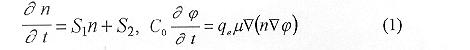 Here
Here  is a capacitance of the shielded tube, per unit of central channel
volume, where FIW moves. C0 may be a function of the coordinate x, m is the mobility of the electrons, qe is the electron charge, n is the electron density, j is the electrical potential. is a capacitance of the shielded tube, per unit of central channel
volume, where FIW moves. C0 may be a function of the coordinate x, m is the mobility of the electrons, qe is the electron charge, n is the electron density, j is the electrical potential.
Equations of the non-linear system (1) couple to each other through the
"effective" ionizing frequency  and the mobility of the electrons and the mobility of the electrons  , that strongly depend on the module of the electric field strength, and the electron density. It is impossible to obtain an analytical solution of the non-linear system of equations (1) for an arbitrary dependence of ionizing frequency on the electrical field strength. For the construction of an analytical solution we use a modification of a frequently used approach, which consists of considering the effective ionization frequency and the electron mobility as a constant but that depends on the maximum of electrical field strength in the front of the wave:
n = n(E0) = const, if E > E1 and n = 0, if E < E1,
m = m (Eo) = const, if E > E1 and m = 0, if E < E1. (2) , that strongly depend on the module of the electric field strength, and the electron density. It is impossible to obtain an analytical solution of the non-linear system of equations (1) for an arbitrary dependence of ionizing frequency on the electrical field strength. For the construction of an analytical solution we use a modification of a frequently used approach, which consists of considering the effective ionization frequency and the electron mobility as a constant but that depends on the maximum of electrical field strength in the front of the wave:
n = n(E0) = const, if E > E1 and n = 0, if E < E1,
m = m (Eo) = const, if E > E1 and m = 0, if E < E1. (2)
In the approximation (2) the electrical field strength E1 could be found from the known dependency of ionizing frequency ni(E) on the electrical field strength; E1 depends only on the sort of gas and the gas pressure. Approximation parameter E1 is the same for all FIW of different intensity propagating in the given gas and under the same gas pressure. The approximation parameter E0 is determined by processes of the given problem and depends on the distinctive parameters of the problem (for instance, an electrical potential of the high-voltage electrode) and will be different for all FIW of different intensity propagating in the given gas and the given gas density. This difference is due to the fact that an ionizing frequency ni(E0) is a function of the electrical field strength in the front of FIW, of the type of gas and the density of working gas.
In the system (1) the terms S1 and S2 that describes the dusty particles influence gases are present. There significant is following: S1 = ni-na-np (3)
Here ni is the direct ionization frequency of the gas; na is the attachment frequency of electrons on molecules of gas; np is the attachment frequency of electrons on particles of condensed phase. np can be written in the form :

where r is a radius of particles condensed phase (we consider that condensed phase consist of identical particles), m is a mass of electron, Np is a condensed phase concentration. S2 is the rate of electron emission from the condensed particles per the unit of time.
The self similar solution of the system (1) is found in the coordinate system, connected with the front of wave using the self similar variable

where w is a velocity of FIW; the point x = 0, in which  corresponds to the structure of FIW front. corresponds to the structure of FIW front.
Using the self similar variable x = x- wt system (1) looks as follow:
 E(x) has a minimum in x=0. The FIW velocity in dusty plasmas can be represented by the following formula:

Theoretical dependencies of FIW velocity on the gas pressure for pure nitrogen (the curve 1) and nitrogen (the curve 2) with dust particles are presented on Fig. 1.

CONCLUSIONS
Within the framework of the proposed models using analytically obtained
formulas {11) it is possible to find: dependency of the FIW velocity on the amplitude of high voltage potential and from building-up time of the high-voltages potential, on efficient permeability of surrounding matter and, mainly, on the pressures of gases, and concentration of dust. Obtained analytical formulas correlate quantitatively with experimental results for pure gases within the accuracy of experiments [3].
REFERENCES
- Sinkevich, 0. A. and Trophimov, Yu. V., On spreading mechanism
of breakdown wave in weak ionized plasma in nanosecond discharges, Dokl. Acad. Nauk SSS, Vol. 249, pp 597-600, 1979 (in Russian), Soviet Phys Dokl, Vol. 249, pp 935-938, 1979 {in English).
- Sinkevich, O. A. and Traphimov, Yu. V., The theory of secondary breakdown waves, in "Problems of physics and technique of nanosecond electrical discharges", Inst. of High Temperature Acad. Nauk USSR, Editor Asinovsky, E. I., pp 55-75, 1982, (in Russian)
- Sinkevich, O. A. and Gerasimav, D. N., Super-high speed ionizing waves in long shielded tubes, Prac. XXIII Int. Conf. on Phenom. in Ionized Gases, Tauluose, France, 1997. Vol.5, pp 20-21.
NEW EQUILIBRIUM
NUMERICAL MODEL OF PLASMA FORMATION
IN TWO-ELECTRODELY GAP WITH THE COLD CATHODE
Arefjev A. S., Antoshkin V. A., Senin P. V., Yudaev Yu. A.
Ryazan State Radioengineering Academy, Russia
At a built-up of a plasma formation in two-electrodely gap with the cold cathode
model the following phenomena were taken into account:
surface, causing an emission of particles from the cathode under the g processes action and their drift;
- space a processes, defining origin and accumulation of charges into the gap;
- driving particles in the space under the influence of an electrical field created by
potentials on electrodes and a space charge of components of plasma.
The analysis of physical processes which are flowing past at the formation of a
discharge has allowed to make the following assumptions of a numerical model:
- the magnitude of a current which is flowing past through the discharge gap, is
determined by maximum admissible concentration of electrons at the given voltage on the
anode;
- temperature of the cathode is constant in time (power from a discharge, it is not
taken into account);
- no emission from the cathode, except for a secondary electronic emission;
- the concentration of neutral gas is uniform all over the gap and does not vary
during the discharge formation;
- the drift velocities of ions and electrons are determined by an electrical field and
collission processes;
- the potential distribution inside the interelectrodely gap is determined by the
voltage on electrodes and the space charge of components of plasma;
- the ionization by secondary electrons is taken into account by the collection them
in uniform monoenergetic groups.
The comparison of impulse performances taken from the experimental make-up
with outcomes of simulation has shown the good agreement of results in a range of
pressure variation 0<P<1500 Pa; voltages on the anode 0 < Ua < 3000 V; current
densities 0 < j < 103 A/m2.
In the mentioned above range of discharge conditions the outcomes of numerical
simulation will be good agreeed with quantitative performances of physical experiment.
NONLOCAL TRANSPORT OF ELECTROMAGNETIC SIGNALS IN INHOMOGENEOUS
PLASMAS
Nikolai S. Erokhin* and Anatolii K. Nekrassov**
* Space Research Institute of Russian Academy of Sciences, Profsouznaya Str.84/32, 117810
Moscow, Russia.
Fax : (7)-095-310-7023; E-mail : nerokhin@mx.iki.rssi.ru
** United Institute of the Earth Physics of Russian Academy of Sciences, B.Gruzinskaya Str.10,
123810 Moscow, Russia
The nonlocal transport of electromagnetic signals in inhomogeneous plasmas by modulated charged
particle microscopic streams is considered. This problem is of interest for the thermal plasma diag-
nostics, for the plasma wave barriers transillumination and nonlocal excitation of electromagnetic
fields in plasmas also. The main purpose of present paper is to study theoretically the influence of
regular plasma inhomogeneity ne(x) ( where ne(x) is the plasma density ), maintained by the polarization electrostatic field with the potential F(x), on the kinetic effects like linear and nonlinear
plasma echoes.
The probem formulation can be described as the following. The external electromagnetic sources S1
with electric field E1 d( x - x1) cos w1 t and S2 with electric field E2 d( x - x 2 ) cos w2 t , localized
at points x1 and x2 ( where d(x) is Dirac function ) at the fixed frequencies w1 and w2 produce in a
thermal plasma the modulated microscopic streams of charged particles. In our case when frequencies w1 and w2 are of the order of the electron langmuir frequency wpe , they are electron
streams. Due to the thermal spread in charge velocities, the electric fields generated by these sources
in the plasma are damping at small distances from the sources. Usually, these distances are of the
order of debye radius. Nevertheless, due to both the plasma inhomogeneity and the plasma
nonlinearity, the nonlocal excitation of macroscopic electromagnetic fields on the source frequencies
w1 , w2 and the sum w4 = w1 + w2 and the difference w 3 = w1 - w2 frequencies also takes place.
Moreover, the spatially localized electric field splashes may be generated in the opaque plasma
regions and behind the wave barriers also.
To study the phenomena described above, the kinetic theory based on the Vlasov equation for the
electron distribution function f e (x, t,e), where e = me v2 /2 - e F(x) is the electron energy, is
developed. It is investigated the plasma inhomogeneity features necessary to realize the nonlocal
effects observed in the inhomogeneous plasma only, namely the linear echo and the sum frequency
nonlinear one. In particular, a number of the spatial profiles of equilibrium electrostatic potential
F(x) satisfying to the condition of observability of the linear plasma echo and the nonlinear sum
frequency one is given by analytical expressions. It is noticed also the interesting possibility to have
the double linear plasma echo from the single source. Then the dependence of nonlocal transport
efficiency and echo positions on the typical plasma parameter values is studied.
To characterise the effect of plasma inhomogeneity on the phenomena studied it is introduced the
new parameter c which determines the inhomogeneity influence on the nonlinear difference frequency echoes of the second order on source amplitudes. For the small value of parameter c , the
smooth transition to the case of homogeneous plasma echoes is demonstrated. The dependence of
the second order plasma echoes on the parameter c value is obtained. The nonlocal generation of
spatially localized electric field splashes by the external electric sources S1,2 in the opaque plasma
regions is analyzed.
Finally, the possible applications of the effects considered to laboratory and space plasma conditions
are discussed.
THE ENERGY TRANSPORT BY ELECTROMAGNETIC WAVE BEAMS INTO AN
INHOMOGENEOUS OVERDENSE PLASMAS
Nikolai S. Erokhin and Nadezhda N. Zol'nikova
Space Research Institute of Russian Academy of Sciences, Profsouznaya Str.84/32, 117810
Moscow, Russia.
Fax : (7)-095-310-7023; E-mail : nerokhin@mx.iki.rssi.ru
The waveguide propagation of powerful electromagnetic wave beams in the weakly inhomogeneous
nonlinear plasmas is considered both analytically and numerically.
The self-consistent mathematical description of this nonlinear problem for the case of quasi-
monochromatic electromagnetic wave packet is given in terms of the axial ray path Ra(s) where s is
the arc length along the axial ray path, the soliton's type of electromagnetic wave beam structure A0
(r,s) in the plane perpendicular to axial ray, the longitudinal wave number kII (s) and variations of
relevant wave beam parameters ( for example, the beam radius rb (s), the maximum field intensity Em
(s) and so on ) along the wave beam trajectory. The approach developed corresponds to the thin
wave beam interaction with inhomogeneous plasmas which means that the beam diameter 2rb is small
in the comparison to the typical inhomogeneity length of plasma density L ( thus the dielectric
constant of inhomogeneous background plasma is determined by a some function e(r/L) where r is
the radius-vector ).
The principal factors of the problem considered, namely, the plasma nonlinearity and plasma inho-
mogeneity, are taken into account under considerations. The approach used gives the possibility of
significantly simplified description of a wave beam propagation in the inhomogeneous plasma and
allows to study also the transport of electromagnetic energy by wave beams ( or by the other word -
the transport of electromagnetic energy in narrow filaments ) for a number of plasma nonlinearity
models including the ponderomotive one with the nonlinearity saturation.
The basic parameter of calculations performed which determines the wave beam behaviour in inho-
mogeneous plasmas is the value of electromagnetic energy flux P transported by the wave beam.
Under the dissipative factors neglecting, the power P is conserving along the axial ray path.
It is shown that due to the strong nonlinearity the narrow filament is forming in inhomogeneous
plasmas by the powerfull electromagnetic wave beam. Such beams conserve their structure because
the diffraction spreading is suppressed by the nonlinearity and they may penetrate into the overdense
plasma region without a significant speading. The decreasing of ray path curvature under the wave
apmlitude growth ( the so-called ray path "straightening" ) is demonstrated numerically. Therefore,
the energy of incident electromagnetic wave beam can be transferred into the dense plasma ( the
opaque plasma region in terms of the linear theory of electromagnetic wave propagation in inhomogeneous plasmas ) where it results, in particular, to the plasma heating.
The appearance of screening surface in the overdense plasma region and its influence on the wave
beam penetration into the dense plasma is analyzed.
The dependence of energy transport on the plasma and wave beam parameters, the nonlinearity and
plasma inhomogeneity models is discussed. In the case of power law for the nonlinear part of the
dielectric constant e, the simple scalings for relevant wave beam parameters are obtained.
The possible application of theory developed to the plasma heating problem in common and , in particular, to the laser plasma conditions is argumented.
ON POSSIBLE NONISOTHERMALITY OF DUSTY PLASMA
I.S.Altman
The Institute of Combustion & Advanced Technologies, Odessa State University,
Ukraine, 270026, Odessa, Dvoryanskaya, 2.
e-mail: vov@ictg.intes.odessa.ua
The systems which appear during combustion of the different fuels can be considered as the low-
temperature gaseous plasma with condensed dispersed phase. The typical size of the condensed
particles within such plasmas is about 0.03 mm for hydrocarbon flames where the soot particles are
formed1 and is about 0.1 mm for metal dust flames where the oxide particles are formed2. For
understanding of the processes of these particles formation it is necessary to describe adequately the
heat transfer between the forming particles and the gaseous phase. Indeed, for example, the energy
releasing by the one oxide molecule absorption on the surface of the growing oxide particle is about
5-10 eV. The main channel of this energy removal is radiation, which controls the condensation rate3-5. However, the leading role of the radiative energy removal observed experimentally indicates a
practical absence of the conductive heat transfer between the particles and a gas.
Since the conductive heat transfer between the small particles and the gaseous phase occurs in free-
molecular regime, the efficiency of conductive heat transfer depends on the value of the so-called
energy accommodation coefficient (EAC)6. The methods of EAC calculation can be classified as
classical methods and methods using quantum mechanics. The analysis of the classical consideration
of the gas molecule collisions with condensed particles (which is made in the present work) shows
that classical approach leads to obtain the results violating to the second law of thermodynamics.
Therefore, the known6 classical results for the value of EAC are wrong. The quantum approach to
calculate the value of EAC requires the modeling of quantum probabilities. The assumption usually
made at this modeling leads to a loss of generality. However, the high-temperature estimation of
EAC can be obtained only on the base of the detailed balancing principle without any model
assumptions . This estimation7 shows that the value of EAC is less than  , where i is the
number of degree of freedom of a gas molecule; Tg, Ts are the temperatures of the gas and the
condensed particle correspondingly; Q is the Debye temperature of the particle substance. For the
typical combustion temperatures EAC is less than 1/600. Therefore, the small particles within plasma
are practically thermally isolated from the gas. , where i is the
number of degree of freedom of a gas molecule; Tg, Ts are the temperatures of the gas and the
condensed particle correspondingly; Q is the Debye temperature of the particle substance. For the
typical combustion temperatures EAC is less than 1/600. Therefore, the small particles within plasma
are practically thermally isolated from the gas.
The small values of EAC leads to the possibility of the essential difference between the gas and small
particles temperatures. The estimations made in the present work show that in flames this difference
can be more than 500 K. This difference is caused by the oxide condensation in metal flames and by
the soot combustion in hydrocarbon flames. The value of the temperature difference varies during
the oxide particle growth and the soot particle burn-out. So, the particles of different size within the
burning system have essentially different temperatures.
The particles nonisothermality within plasma can be simply recognized with the help of the spectrum
of plasma continuous radiation. If plasma is optically thin the plasma radiation is the sum of the
single particle radiation. As the fraction of particles with the highest temperature is small, we obtain
from the spectrum the average particle temperature. In this case the plasma emissivity (reduced to
the mean temperature) strongly increases in ultraviolet. That is why, the rate of the observed
emissivity increase in ultraviolet8,9 allows to estimate the level of the dusty plasma nonisothermality.
Thus, in the present work it has been predicted the essential nonisothermality of dusty plasma. We
also discus the possibility of its detection.
This work was partially supported by INTAS (grant 96-2334).
REFERENCES
- Xu, F., Lin K.-C., Faeth G. M., Soot Formation in Laminar Premixed Methane/Oxygen Flames at
Atmospheric Pressure, Combustion and Flame, Vol. 115, pp 195-209, 1998.
- Zolotko, A. N., Vovchuk, Ya. I., Poletaev, N. I., Florko, A. V., Altman, I. S., Nanooxides
Synthesis in Two-Phase Laminar Flames, Fizika Gorenia i Vzryva (in Russian), Vol. 32, No. 3, pp
24-33, 1996 (translated in "Combustion, Explosion and Shock Waves").
- Altman, I. S., On Heat Transfer During Condensation of the Products of Metal Gas-Phase
Combustion, Fizika Gorenia i Vzryva (in Russian), Vol. 34, No. 4, pp 49-51, 1998 (translated in
"Combustion, Explosion and Shock Waves").
- Shoshin, Yu. L., Altman I. S., Experimental Study of Radiation Heat Loses During Single
Magnesium Particle Combustion, Twenty-Seventh Symposium on Combustion (International),
Boulder, USA, August 2-7, 1998, Book of Abstracts, p 256.
- Altman, I. S., Microapproach to Description of Oxide Particles Condensation Growth During
Metals Combustion, Ibidem, p 258.
- Goodman, F. O., Wachman, H. Y., Dynamics of gas-surface scattering/Academic Press, New
York, San Francisco, London, 1976.
- Altman, I. S., High-Temperature Estimation of Energy Accommodation Coefficient, submitted in
Physica A.
- Florko, A. V., Altman, I. S., Poletaev, N. I., On Possibility of End Product of Aluminium and
Magnesium Combustion Dispersivity Determination by Radiation Spectrum (in Russian), Tenth
All-Union Symposium on Combustion and Explosion, Chernogolovka, Russia, September, 1992,
pp 79-81.
- Block, B., Hentschel, W., Ertmer, W., Pyrometric Determination of Temperature in Rich Flames
and Wavelength Dependence of Their Emissivity, Combustion and Flames, Vol. 114, pp 359-369,
1998.
THE METHODS OF CALCULATION OF THERMAL AND ELECTROMAGNETIC PARAMETERS OF
HIGH FREQUENCY DISCHARGE IN GAS INDUCTION HEATING
R.N.Gainullin, A.R.Gerke
Kazan State Technology University, Kazan, 420015, Russia
To create and to optimise high frequency induction (HFI) plasma reactors it is necessary to
dispose information about basic electromagnetic and thermal parameters in the zone of a discharge and,
especially, about temperature. A method based on the data of the active zone magnetic measurements
has good prospects to analyse HFI discharge.
Proposed methods consist in a use of results of plasma magnetic field measurements for a
solution of the Maxwell's equations system. One can introduce a transformed Maxwell's equations
system in the following way:

To solve (1) most investigators use entrance information based on parameters, e.g. inductor
current intensity or power put in the discharge, measured in the plasmotron primary chain. Since these
magnitudes do not have a monosemantic connection with a temperature in the zone of the discharge, it
is necessary to use an additional equation. Usually it is an equation of the energy balance.
If one applies results of magnetic measurements it allows one not to use additional dependencies.
Variation of a value of the magnetic field by the discharge cross-section is determined by the
electromagnetic energy absorption in the gas-conducting layer. Therefore, it is electrical conductivity of
gas that determines a velocity of variation of the magnetic field value by the discharge radius in a case of
other equal conditions. The use of this dependence allows one not to apply additional equations and to
solve a problem being in the frames of the Maxwell's equations system. If to expand this system with
dependencies for the temperature and the specific capacity of heat-excretion like this T(s) and W=s*E2
then its solution allows one to obtain information about the two-dimensional profile of the
basic thermal and electromagnetic parameters of HFI discharge.
The measurements of the magnetic field have been varied out at the plasmotron of the capacity
of 60 kWt at the frequency of 1.76 MHz. The discharge camera of 76 mm in diameter have been made
of quartz. The special water-cooling magnetic probe permits prolonged operation in the conditions of
high temperatures which are characteristic of such kind of discharge. Radial distributions of the axial
magnetic field strength (Fig.1) have been obtained in various cross-sections by after the magnetic
measurements carried out in dicharges in the air.

Experimental data have been smoothed and fitted by the two-dimensional spline which have been
then used in calculations. The quality of fitting has been additionally checked by the character of
variation of the first and second derivatives of the function Hz(r,z). The spline ensured a smooth
character of the derivative variation in the considered interval of the co-ordinates variation. After
processing of the experimental information radial profiles of the basic electromagnetic magnitudes have
been found with the help of two-dimensional model.
Values of the equilibrium temperature and specific capacity of heat-excretion have been
calculated simultaneously in each integration point using known dependencies of T(s) . On the other
hand, temperature has been experimentally determined by the optical methods of absolute intensities in
the unified cycle with magnetic measurements.
Since experimental information obtained by the optical methods can be measured only in the
plasma regions which are not shadowed by the inductor's spires, the comparison of results of both
methods has been carried out not for all cross-sections.
Figures 2 shows the values of temperature by the z-axis. These data have been compared with
results of the optical measurements where it was possible. Information is given for two modes of
plasma-forming gas of 9 and 13 m3/h . Fig.3 shows variation of specific capacity of heat-excretion by
the z-axis.
One can see that experimental results have sufficiently good coincidence with calculated
parameters. It proves a possibility of the use of the proposed methods as independent diagnostic manner
especially in those cases when application of the other HFI discharge measuring methods is not possible
for some reasons.

PRODUCTION AND STUDY OF HIGHLY IONIZED SUBSONIC PLASMA FLOWS
A.A. Belevtsev, V.F. Chinnov, E.Kh. Isakaev, A.V. Markin
Associated Institute for High Temperatures, Russian Academy of Sciences
Izhorskaya, 13/19, Moscow, 127412, RUSSIA, E-mail: agni@aha.ru, Fax: (095) 4859777
INTRODUCTION
Highly ionized plasma flows hold increasingly promise for being used in diverse scientific researches and industrial applications. Of different ways for their generation, that based on plasma production by a high current electric arc plasmatron has considerable advantages over many others. With this in mind and also with the aim of more deep insight into plasma flows physics, in Associated Institute for High Temperatures of the Russian Academy of Sciences has a powerFul arc plasmatron been engineered allowing an essential progress along the lines mentioned [1]. A major goal of the present paper is to contribute to the study of not ordinary in many respects argon and nitrogen highly ionized plasmas generated in subsonic gas flows nearby the cathode of such a plasmatron. The paper describes some special features of the experimental arrangement, analyzes the spectra emitted, the plasma composition and the radial distributions of radiating particles. Besides, the data obtained permit the basic energy exchange mechanisms to be examined.
 EXPERlMENTAL ARRANGEMENT
An arc plasmatron allowing generation of the plasmas mentioned is essentially comprised of a tip cathode made of thoriated/lanthanated tungsten rod, a copper interelectrode spacer and the anode with a divergent inner channel of 6 mm at the inlet and 26 mm at the outlet, the angle of divergency being 12°. The anode is built up either as a solid copper water cooled taper or a stack of individual water cooled segments. There in the anode windows 10 mm in height and 1 mm wide are designed to observe the plasma transversely at different distances z away from the cathode. The gas to be ionized was fed tangentially into the interelectrode spacer zone at flow rates G=1-5g/s. Used were Ar and N2 at atmospheric pressure. The arc length was 20-30 mm at currents of 150-400A and the voltage drops across the arc were 40-50V in Ar and 70-100V in nitrogen providing high specific energy release ( >50kW/cm3 ) and the electron component parameters Te > 2eV, ne > l017cm3 nearby the cathode. The plasma flows show, by and large, high stability and their geometric and thermophysical parameters are well reproduced. For spectral measurements two recording systems were used, one involving diffarction grating DFS-452 with two photodiode arrays Toshiba 1250A and the other being based on monochromator MDR-41 with photoelectric multiplier FEU-100. Further details concerning the setup and the measuring systems can be found in [2]. To process spectrometric data an automated system based on package MathCad was developed with using high effective PC allowing extensive data files (up to 10 Mb per experimental cycle) to be created as well as securing of a great body information on physical characteristics of spectral lines emitted by atoms, singly and doubly charged ions, first of all on radiative transition probabilities Aki and the Stark broadening constants wSt. The system also permits the Abel inversion and simulating rotational structure of molecular vibronic bands, the latter making it possible to determine distributions over vibrational and rotational degrees of freedom.
RESULTS
The radiation emitted from a gas volume nearby the cathode (z=4-5mm) has been investigated with a high spectral resolution in the 200-1000nm wavelength interval spanning the near IR- and UV-regions. In the UV-wing, ArII and NII lines dominate, though ArIII and NIII lines are also present
in quantity. The essential is that narrow and not practically shifted ionic lines allow the spectra taken to be precisely related to the wavelength axis. A typical UV- spectrum fragment, as applied to N2, is shown in Fig.1. It is only within a narrow spectral region (250-265nm) that N2D3Su+-B3Pg3 and N2+D2Pg- A2Pu molecular systems contribute appreciably to the total intensity. Conversely, in the near IR-region, ArI and NI lines are principally observed. As an example, Fig.2 displays a fragment of Ar IR-spectrum. Radial spectral intensity distributions el(r) were being determined with the side-on observations followed by the Abel inversion. A characteristic profile for singly charged Ar ions can be seen in Fig.3.
Within the spectral region investigated there exist wavelength intervals containing together closely spaced spectrally resolvable lines originated from different stages of ionization. This made it possible to derive the electron temperature Te by the ratios of relative line intensities [3]. The electron concentration ne has been evaluated from atomic and ionic line half widths with using the known Stark constants [4]. To obtain excited species populations the measured absolute intensities Iki and the available data on the Einstein coefficients Aki [5] were used. As a whole, what the plasma investigated remarkably features is that the concentrations of singly and doubly charged ions are close to each other (n+ ~ n++) and to those of excited atoms n* and attain high values ~ 1012-1014cm-3. From the el(r) dependences (see Fig.3), radial variations of the excited radiating components have been determined too. Finding Te(r) dependences turns out much more complicated task and involves a detailed analysis of departures from LTE or/and partial LTE conditions. Nevertheless certain physically reasonable conclusions have been possible.
Based on the quantities, both the measured and calculated, the paper further considers energy balances in Ar and N2 plasmas in question. A radiative transfer and that due to thermal and mass fluxes onto the walls are taken into account. An important role of electron-ion collisions in dissipating the electron gas energy within the spatial domain near the cathode is pointed out.
REFERENCES
- Zobnin, A.V., Isakaev, E.Kh., Iserov, D.A., Kalinin, V.I., Tereshkin, S.A. and Chinnov, V.F., Emission Spectra of a High Current Disharge in the Divergent Channel Plasmatron, Preprint No. 1-405/Institute for High Temperatures, Russian Academy of Sciences, Moscow, 1997, p 33.
- Belevtsev, A.A., Chinnov, V.F. and Isacaev, E.Kh., Radiation and Parameters of High Enthalpy Nitrogen Plasma Jets in the Relaxation Zone, Proceedings of 1lth Symposium on Elementary Processes and Chemical Reactions in Low Temperature Plasma, Low Tatras, June 22-26, 1998, pp 183-187.
-
Plasma Diagnastics, Ed. Lochte-Holtgreven, W./ Noth-Holland Publ. Co., Amsterdam, 1968.
- Konjevic, N. and Roberts, J.R., A Critical Review of the Stark Widths and Shifts of Spectral Lines from Non-Hydrogenic Atoms, J.Phys.& Chem. Ref. Data, Vol.5, No.2, pp 209-311, 1976.
- Wiese, W.L., Smith, M.W. and Glennon, B.M., Atomic Transition Probabilities, Vol.l,2, Natl. Stand. Ref. Data Ser./Natl. Bur. Stand., USA, p4, 1966.
INVESTIGATION OF ELECTRONICALLY EXCITED SPECIES IN HIGH ENTHALPY NITROGEN PLASMA JETS
A.A. Belevtsev, V.F. Chinnov, E.Kh. Isakaev, A.V. Markin
Associated Institute for High Temperatures, Russian Academy of Sciences
Izhorskaya 13/19, Moscow, 127412, RUSSIA, E-mail: agni@aha.ru, Fax: (095) 4859777
INTRODUCTION
Physical studies of high enthalpy molecular plasma jets have attracted considerable interest induced by new plasma-used technologies brought into practice in recent years. Of different aspects related, that dealing with electronically excited species seems to be one of the most important because it is those plasma components that appear to play the determining role in occuring numerous technological jet-aided processes. The surprising thing is, therefore, that the relevant information so far obtained is rather scarce. A major focus of interest for the present paper is to reveal basic electronically excited atomic and molecular components, both neutral and charged, produced in high enthalpy subsonic atmospheric pressure nitrogen plasma jets and to study their spatial distributions along and transversely the jet. How the gas flow rate influences is also examined.
 EXPERIMENTAL SETUP
The jets investigated were being produced by a high current (I<500A) plasmatron with a divergent channel-anode vortex stabilized by the working gas. The angle of divergency is 12°, the jet diameter near the plasmatron cathode-6mm, and the gas flow rates G range from 1 to 5 g/s. What to be processed to derive all necessary information about radiating electronically excited states were atomic and molecular emission spectra taken in the 200-1000 nm region with high spectral resolution (~0.01nm) and at different the jet cross-sections. Note that the spin splitting of 2S terms and D-doubling of 3P terms remained however unresolved because of appreciable rotational lines broadening under the conditions investigated. A detailed description of the experimental setup and measuring techniques is given elsewhere [1]. The spectra obtained show a rich variety in atomic and atomic ion lines and molecular vibronic bands thus allowing the task set to be readily solved. Fig.l may serve a good illustration to the preceding displaying clearly both linear and band spectrum constituents against a fairly intensive continuous background. To process experimental data an automated system has been developed based on package MathCad which allows the distributions over electronic, vibrational and rotational degrees of freedom to be investigated.
RESULTS
Concentrations N*, (N+}*, (N++)* of nitrogen atoms and atomic ions have been derived from absolute intensities Iki of lines with using known Einstein coefficients Aki [2]. A purpose-developed procedure was also applied to separate the contributions of two neighbouring partly overlapped spectral lines. Quantities ln(lkiIki / Akigk), when plotted against Ek for higher energy levels (lki, gk, Ek are the transition wavelength, the k-th level deneracy and energy, respectively), allowed excitation temperatures Ta*, Ti* to be found. Given those Ta*, Ti* and the obtained concentrations as well as electron temperature Te deduced from relative intensities of ionic lines originated from different stages of ionization, the particle densities of atoms and atomic ions in their ground states were then estimated with allowance made for generally non-equilibrium distributions over low-lying energy levels [3].
To calculate concentrations of N2(C3Pu) and N2+(B2Su+) in different vibrational states, vibrational Tv and rotational Tr temperatures should be previously determined. To this end the methods af relative integrated intensities of vibronic bands [4] and simulating rotational structure of electronic transitions were used. In the far plasma relaxation zone, often more convenient was to determine populations through an integrated intensity of the vibronic band segment "cut out" in the vicinity of the band head.
All the spectra being taken at different distances away from the plasmatron cathode, this has enabled the radiating plasma component distributions along the jet to be determined. To study their radial variations the Abel inversion has been applied. What the typical emission intensity profiles are can be inferred from Fig.2.
Much more complicated turns out the problem of determining concentrations of electronically excited metastable nitrogen components. Of atomic ones, those are N(2P), N(2D). Among molecular metastables, N2(A3Su+), N2(a'lSu-), N2(a"Sg+) are of foremost importance. Suffice it to say in this connection that it is due to pair ionizing collisions between metastable molecules, e.g.,

that charged particles make their appearance at distances well removed away from the cathode where electric field and current are absent. To assess metastable concentrations the particle density balance equatians are examined with both radiating and metastable species being invaked. Despite the wide scatter in data on the metastable-assisted reaction rate constants, especially at high gas temperatures, it has been possible to obtain certain quantitative estimates. By the same procedure an information can also be obtained on electronically excited radiating nitrogen components, e.g. N2(B3Pg), not manifesting themselves radiatively in the spectral interval investigated.
REFERENCES
- Belevtsev, A.A., Chinnov, V.F. and Isakaev, E.Kh., Radiation and Parameters of High Enthalpy Nitrogen Plasma Jets in the Relaxation Zone, Proceedings of the 11th Symposium on Elementary Processes and Chemicai Reactions in Low Temperature Plasma, Low Tatras, June 22-26, 1998, pp.183-187.
- Wiese, W.L., Smith, M.W., and Glennon, B.M., Atomic Transition Probabilities (H through Ne), Vol. 1, Natl. Stand. Ref. Data Ser./Natl. Bur. Stand., USA, P.4, 1966.
- Plasma Diagnostics, Ed. Lochte-Holtgreven, W. /Noth-Holland Publ. Co., Amsterdam, 1968.
- Herzberg, G., Molecular Spectra and Molecular Structure, Vol.1, Spectra of Diatomic Molecules/Van Nostrand, Princeton, NY, 1950.
NON-EQUILIBRIUM AND SPATIALLY NONUNIFORM PLASMA SYSTEMS
CHEMISTRY
V.Jivotov, V.Rusanov
Hydrogen Energy & Plasma Technology Institute, Russian Research Center "Kurchatov Institute" Kurchatov sqr., 123 182 Moscow, Russia
Non-equilibrium properties of low temperature discharge plasma at the pressure about 0.1-1 ATM is being used widely for plasma chemistry applications. Those discharges are usually strongly spatial non-uniform. Effective non-equilibrium process mechanisms depend on choosing true spatial plasma confýguration and optimal designing active discharge areas. Both the discharge periphery and post-discharge area could be those active areas. One could observe several types of non-equilibrium for spatially non-uniform plasmachemical systems.
Thermal non-equilibrium
Many endothermic chemical processes are being stimulated successfully by nonequilibrium vibration excitation in plasma of molecular gases. In the case of contracted discharge the excess of vibration temperature Tv over the gas temperature T0 (Tv > T0) could be realized namely at the discharge periphery, the main part of a gas flow also passes through the periphery . In the microwave plasma in C02 (the pressure P = 100-200 torr) the equilibrium temperature of the discharge core Tv = T0 = 5000 K. The typical conditions at the discharge periphery: Tv = 2500-3000 K; T0 = 1000-1500 K . Under these conditions the efficiency of endothermic non-equilibrium process of C02 dissociation could achieve 80% (while equilibrium efficiency value of about 45%). The similar situation could be observed in microwave discharge in methane. The low vibration non-equilibrium (Tv on the order of 2500 K at T0 on the order of 1500 K) allows, for example, to decrease energy cost for endothermic process of methane conversion into acetylene from 9 eV/mol (typical for equilibrium arc discharge) to 6 eV/mol- experimental data in non-equilibrium microwave discharge at the pressure 100 torr.
Spatial non-equilibrium
The periphery of a plasma chemical discharge could become the active plasma area under the condition of rotating gas flow while using centrifugal effect. In a plasma in H2S, while realizing the process of H2S dissociation, the dissociation product- the sulfur exists as heavy clusters S2, ... , S8 . As the result of the centrifugal effect the non-equilibrium spatial substance separation takes place. The last one decreases the reverse process influence and set the conditions for the inner recuperation of the energy being given off in recuperation processes S2 -> S8 in the discharge periphery. The summary effect decreases process energy cost up to the value 0.5 eV/molecule (theory) and 0.8 eV/molecule (the experiment with microwave plasma at the pressure 100 torr) by comparison with the value 1.8-2 eV/molecule in the equilibrium case. There is also the grate and specific influence of the discharge periphery in the case of supersonic discharge systems. The strong spatial non-uniformity of those discharges could lead to an appearance of branched boundary between plasma and supersonic gas flow with a very large temperature gradient. Both the plasma area and supersonic gas flow could be active areas of the plasmachemical system- the last one, in particular, as the producer of non-thermostale substances. So, in supersonic microwave discharge in the water vapor, the plasma generates radicals H and OH, the last one is being transferred into cold supersonic flow and produce the hydrogen peroxide with using condensed water phase: OH + OH + M = H202 + M . As a result up to 80% of oxygen (the product water dissociation) is being combined into hydrogen peroxide.
Kinetic non-equilibrium
It is also possible to use non-equilibrium effects of plasma systems in a active postdischarge area while cooling gas and relaxing plasma active particles . The typical example- water vapor dissociation in microwave discharge at the pressure 80 torr. Non-equilibrium transferring of radicals (H, OH) into the product (hydrogen, oxygen) allowed to increase the process energy efficiency up to 40% in comparison 18% in equilibrium situation. In the case of conversion of H2S/C02 mixture into synthesis gas in microwave plasma (the pressure 0.7 atm) the inner energy recuperation, noted above, while cooling gas is post-discharge area, allows to increase the conversion degree (in one and a half times) and to decrease the process energy cost up to the value 1.5 kWh /m3 of synthesis, gas plus 1.4 kg of sulfur. The process is realized at small industrial installation [ 1 ].
Systems with combined energy input
One is dealing with specific influence of the discharge to previously heated reagents. The role of the discharge results in generation active particles (electrons, ions, radicals, clusters, excited particles etc.). The last one expends the heat energy reserved in heated reagents when stimulating chain endothermic reactions. As a result, one could observe acceleration of plasma chemical process, analogously to the catalysis. In the experiment the methane, heated up to 550C, is being treated by the pulse-periodic microwave discharge at 1 ATM (the relation of the discharge power to heating power is small- 1/10) The discharge duration is 1 ms, the discharge is strongly non-uniform. The influence of the plasma led to increasing methane conversion degree (into hydrogen) in three times. Accelerating the endothermic chemical process and expending heat energy is so intensive that reagents' cooling takes place under plasma affect. It is principally important that this temperature decrease doesn't influence on the plasma catalysis process efficiency, since the last one is not checked by the gas temperature, but by the electron temperature of the plasma. The energy effiency of plasmacatalysis process is very high. The discharge energy consumption is only 0.2-0.3 eV/mol.H2 while the enthalpy of the process is 0.4 eV/mol.H2.
REFERENCES
- V.Jivotov, I.Kalachov, V.Rusanov e.a. Natural Hydrogen Sulfide (H2S) - Source of Hydrogen (Plasma Chemical Dissociation).- New Energy Systems and Conversion ,
Universal Academy Press, Inc., 1993 , Tokyo, 123 - 125.
COMPARISON OF EXPERIMENTAL AND NUMERICAL RESULTS FOR
THE DYNAMIC PRESSURE IN AN INDUCTIVE PLASMA FLOW
Olivier Chazot, David Vanden Abeele and Mario Carbonaro
Von Karman Institute for Fluid Dynamics (VKI),
72 Chaussee de Waterloo, 1640 Rhode St Genese, Belgium
INTRODUCTION
A 1.2 MW inductively coupled Plasmatron wind tunnel has been recently designed and built at the von Karman Institute (VKI, Brussels). It uses an 80 or 160 mm diameter inductively coupled plasma (IPC) torch at an operating frequency of 400 kHz. Power is supplied by a solid state (MOS) radio-frequency inverter of high efficiency. 1,2 The facility will be primarily used to test the resistance of thermal protection system for space re-entry vehicles, combustion chambers, turbine blades or ceramic coatings exposed to severe heat loads.
The operation of the wind tunnel requires a good understanding of the complex interplay between-electromagnetic, flow and thermal effects inside its ICP torch. To study the relative role of these effects, a small "mini-torch" ICP wind tunnel (fig: 1 ) was installed at VKI in 1996. It uses a 30 mm diameter torch, driven by a 15 kW vacuum tube radio-frequency generator at 27.12 MHz. This small facility is well suited to study the effect of various torch operating parameters and gain experience in the operation of an ICP facility, as changes in torch geometry and operating conditions can be easily made.
In parallel with the construction of both facilities, various plasma measurement techniques are being developed and a powerful numerical ICP model has been programmed. 3 Based upon modern implicit CFD techniques, the model allows to simulate inductive plasma flows in a wide range of operating conditions. Recently, the model has been successfully validated 4 against a similar code, developed at the Institute for Problems in Mechanics (IPM, Moscow). As a logical next step in the development of plasma measurement tools and in the validation of the numerical code, this contribution presents a comparison between experimentally and numerically obtained results for the dynamic pressure profiles at the outlet of the mini-torch.
PITOT PROBE MEASUREMENTS
Before implementing more advanced measurement techniques, such as spectroscopy, laser Doppler velocimetry or other non intrusive laser based techniques, simple intrusive measurements have been performed in the mini-torch facility. 5 For a first diagnostic of the plasma jet, results were obtained with a special water cooled Pitot probe, which is relatively easy to put into operation. The probe was designed to work in environments in a severe heat transfer. Its dimensions were taken as small as possible in order not to disturb the plasmajet, but large enough to allow an effi cient internal water cooling. Fig. 2 shows a picture of the probe, immersed in the exhaust jet of the mini-torch
 Dynamic pressure measurements were performed and compared to the results of the
numerical simulation. These correspond to dynamic pressure profiles at the exit of the torch for a Argon plasma at different static pressures. Care needs to be taken when interpreting measured values; viscous effects due to the low Reynolds number flow around the probe and effects connected to the internal cooling of the probe bring some deviation from the interpretation of the stagnation pressure with the simple Bernoulli equation. Though some problems remain to be solved, the Pitot probe measurements were already found to give a good and global characterization of the plasma flow in the mini-torch.
Dynamic pressure measurements were performed and compared to the results of the
numerical simulation. These correspond to dynamic pressure profiles at the exit of the torch for a Argon plasma at different static pressures. Care needs to be taken when interpreting measured values; viscous effects due to the low Reynolds number flow around the probe and effects connected to the internal cooling of the probe bring some deviation from the interpretation of the stagnation pressure with the simple Bernoulli equation. Though some problems remain to be solved, the Pitot probe measurements were already found to give a good and global characterization of the plasma flow in the mini-torch.
NUMERICAL CALCULATIONS
Numerical calculations of argon plasmas inside the VKI mini-torch (2.4 kW, 27 MHz) have been performed at various operating pressures and for different mass flow rates (Fig.3). The governing resistive MHD equations are discretized in a second order finite volume manner on a structured mesh. The electromagnetic field is discretized on a far field mesh, which extends into the space around the torch, but coincides with the flow field mesh inside the torch. The discretized system of equations is solved through a damped Newton iterative method. Modern Krylov subspace methods are used to efficiently solve the linear systems arizing in the Newton linearization. For now, the calculations were run with an equilibrium model. The model is currently being extended to include non-equilibrium effects.
SUMMARY
As a step in the development of a cooled Pitot probe and a numerical ICP model at VKI, this contribution presents a comparison of experimental and numerical results for the dynamic pressure at the outlet of the VKI mini-torch facility. Comparisons are performed for Argon plasma at various operating pressures with a straight injection configuration. It can be seen that the results start to be in accordance when the pressure increases and the plasma flow comes closer to equilibrium. Thus, the measurements with the probe and of the results predicted by the numerical model can be discussed and assessed.
REFERENCES
- Bottin, B.; Carbonaro, M.; Decre, M.; Mazauric, S.; Novelli, A., Design of a new inductively-coupled plasma wind tunnel for re-entry material testing at the von Karman Institute, Wind Tunnels and Wind Tunnel test techniques, Cambridge, April 1997.
- Bottin, B.; Carbonaro, M.; Paris, S.; Van Der Haegen, V.; Novelli, A.; Vennemann, D., The VKI 1.2 MW Plasmatron facility for the thermal testing of TPS materials, 3rd European Workshop on Thermal Protection Systems, ESTEC, Noordwijk, the Netherlands, March 1998.
- Vanden Abeele, D. and Degrez, G., An efficient numerical model for inductive plasma flows, AIAA Technical Paper 98-2825, Albuquerque, New Mexico, June 1998.
- Vanden Abeele, D.; Vasil'evskiy, S.A.; Kolesnikov, A.F.; Degrez, G.; Bottin, B., Code-to-code validation of inductive plasma computations, Proc. 5th European Conference on Thermal Plasma Processing, St. Petersburg, July 1998.
- Chazot, O.; Pereira Gomes, J.M.; Carbonaro, M., Characterization of a "Mini-Plasmatron" facility by Pitot probe measurements, AIAA Technical Paper 98-2478, Albuquerque, New Mexico, June 1998.
MODELLING AND MEASUREMENTS OF
PARTICLE IN-FLIGHT CHARACTERISTICS OF ATMOSPHERIC
PLASMA SPRAYED YTTRIA STABILISED
ZIRCONIA
Per Nylén,* Rodolphe Bolot **, Anita Hansbo* and Christian Coddet**
*University Trollhättan/Uddevalla, Box 957, S-461 29 Trollhättan, Sweden
**LERMPS-IPSe, BP449, 90010 Belfort, Cedex, France
Stabilised ZrO2 particle in flight characteristics in an Ar-H2 atmospheric plasma jet has been studied
using analytical and experimental techniques. A commercial code was used to simulate the plasma
flow. Powder particle velocity, temperature history and trajectory were calculated, using a
stochastic discrete particle model, and compared with measurements. A good correlation was found
between predictions and measurements. Relationships between the sprayed particle velocity,
temperature and size was investigated. The presented method has the potential to become a
powerful and cost-effective tool to optimise spray parameters off-line.
INTRODUCTION
The plasma spray process is composed of three separate processes: the plasma generation, the
plasma/particle interaction and the formation of the coating. The characteristics of the particles prior
to impact, such as velocity and particle state (i.e. partly or fully molten) are probably the most
important factors influencing the microstructure and properties of the coating. At each production
set-up, variations in the spray parameters, such as powder, nozzle, gas properties, environment,
robot tolerance, etc., might lead to variations in particle characteristics at impact, and thus also to
variations in coating properties. Modern techniques have made it possible to observe the particles in
flight and determine their properties. This on-line measurement of particle properties has the
potential of becoming an efficient diagnostic tool for controlling the plasma spray process. By
moving the control of the process as close as possible to the coating, uncertainty of uncontrollable
parameters is reduced and an increase in process stability and quality standards may be achieved.
To develop such an operator control strategy a moderately complex model linking a few spray gun
parameters with particle in-flight characteristics is needed.
In this paper, the particle flow field of plasma sprayed yttria stabilised zirconia has been
investigated. One aim of this work is to validate the proposed model. Further, the relationships
between the sprayed particle velocity, temperature, and size, are investigated.
EXPERIMENTAL
The distributions of particle temperature, velocity, and size, were measured using the DPV2000
developed by the National Research Council of Canada/Tecnar Automation Ltée system. This
system is based on the detection of thermal radiation from the sprayed particles by an optical
sensor, located perpendicularly to the spray jet, and consisting of a focusing lens and optical fibres.
The DPV2000 measures the parameters of in-flight particles in a volume (200 µm x 300 µm x 2.5
mm) along the optical axis. The particles were measured in a plane located 80mm from the nozzle
exit, in a square of 13 points. The centre point of the square was located at the centre of the particle
flux, about 4mm off the symmetry axis of the plasma plume.
Plasma spraying was carried out using the F4 gun from Sulzer Metco controlled from a Sulzer
Metco A3000S system (automated and robotised). A commercially available powder (8 % yttria
partially stabilised zirconia powder) was used, and the powder was injected radially 6 mm
downstream from the nozzle.
SIMULATIONS
To get a reasonably simple model with short computation time, a commercial code (Phoenics) was
used for the numerical solution of the axisymmetric incompressible Navier-Stokes equations in two
space dimensions, with standard k-epsilon turbulence model, to simulate the plasma flow. In these
calculations, a mass fraction conservation law was used to take interdiffusion effects between the
plasma and surrounding air into account. An in-house code was used for the particle property
calculations. In these calculations, allowance was made for non-continuum effects, internal heat
conduction, phase changes, particle vaporisation and the effects of variable plasma properties in the
plasma boundary layer. The particle model is stochastic in the sense that the initial particle
velocities were assumed to have a Gaussian distribution and that the injections points were
uniformly distributed. Simulations were performed with the same operating conditions as for the
measurements. The plasma simulation was first run to steady state in the absence of particles, and
the resulting solution was then used for the particle spraying simulation.
CONCLUSION
In comparing the measurements and the simulation results, the proposed method gave good
correspondence between predicted and measured average particle temperatures and velocities, cf.
Table 1. The values represent measured and calculated averages for particle diameters of 10-50 µm.

Also, the correspondence between the distributions of these variables is reasonable, cf. Fig. 2 and
Fig. 3. However, the dispersion in the measurement results is larger. This is probably due to the
simplified assumptions of the injection characteristics. It has been shown that there is in fact a
particle size segregation within the injector tube, giving different injection velocities for different
sizes. Instead of sampling from a single distribution, different distributions for different size groups
may be used. This will be considered in future work.
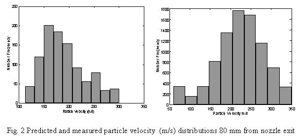

In the simulations, the particle sizes are clearly correlated to the surface temperatures and the axial
velocities, as can be seen in Fig. 4. This is consistent with the intuition that the larger, heavier
particles appear farthest from the injection location with lowest velocities and temperatures.

|


