SESSION 3
APPLICATIONS INCLUDING WASTE TREATMENTS
| Chairman: | J. Heberlein
M. Boulos
|
METALLURGICAL APPLICATIONS OF THERMAL PLASMA ARCS: THE ELECTRIC ARC FURNACE TECHNOLOGY
Prof. Dr.-Ing. Dieter Neuschütz
Lehrstuhl für Theoretische Hüttenkunde
Rheinisch-Westfälische Technische Hochschule Aachen, D-52056 Aachen, Germany
By far the most important technical application of high power thermal plasma
arcs is the electric arc furnace (EAF) technology predominantly used in
steelmaking. In 1997, 256 mio t of steel were made in the EAF representing
33% of the total world steel production. Further metallurgical applications of
thermal plasma arcs are the production of ferroalloys, the treatment of liquid
steel in ladle furnaces and tundishes, and the recycling of chromium-containing
dusts. In specific cases, metallic plasma torches are used as arc generators, but
in most cases graphite is the preferred electrode material.
While tungsten and copper as electrode materials have a lower wear rate per
electricity unit than graphite, electrodes made from high quality graphite have a
much higher current carrying capacity reaching 150 kA for the largest
commercial DC electrodes as compared to 10 kA for tungsten.
The keynote lecture will give an overview of present metallurgical applications
of high power arc systems and will concentrate on the electric arc furnace
technology for steelmaking. The growing role of EAF steelmaking since 1960 is
described as well as the development of the process from a simple scrap
melting technology for reinforcing bar to a sophisticated process for quality strip
production. Modern EAF plant structures with consumption and production
figures are presented for long and flat steel products. Scrap availability and
quality are discussed together with modern process developments to produce
scrap substitutes as direct reduced iron and hot metal from processes other
than the blast furnace. The role of thin slab casting for the use of EAFs to
produce steel strip is discussed.
A comparison of DC and AC arc furnaces is presented together with a
description of presently available maximum power graphite electrodes. The
possibility of shielding the arcs in foaming slag is described. Finally the effect of
molecular gas injection into the arc on the arc voltage and on the steel analysis
is described and discussed in view of a further power increase of EAFs.
PLASMA DESTRUCTION OF GASEOUS AND LIQUID WASTES
A. B. Murphy
CSIRO Telecommunications and Industrial Physics, P.O. Box 218, Lindfield NSW 2070, Australia
Waste destruction systems using thermal plasmas as the heat source are now being implemented on
a commercial basis in many countries. Advantages of plasma-based systems over conventional
incinerators include higher temperatures, shorter residence times, and independence of the heat
source from the waste being destroyed. Systems based on transferred arcs are usually applied to
solid wastes, whereas those based on non-transferred arcs or inductively-coupled plasmas can,
depending on the configuration, be applied to gaseous, liquid or solid wastes. Examples of
industrial-scale plasma waste destruction systems include the Plasma Arc Centrifugal Treatment
(PACT) system developed by Retech, USA, which is a transferred-arc process in which the waste is
contained in a spinning cupola1, and the dc non-transferred arc processes developed by
Aerospatiale, France to treat asbestos waste and fly ash2.
The PLASCON system, developed by CSIRO and SiddonsRamset Plasma Ltd, is based on a
non-transferred arc, and has been successfully applied to the destruction of a range of hazardous
liquids and gases. A schematic diagram of the PLASCON process is shown in Figure 1. An argon
plasma jet is produced using a 150 kW dc plasma torch. The liquid or gaseous waste is injected,
together with an oxidising gas, through an injection manifold downstream of the anode. The
resulting mixture of hot gases passes through a reaction tube, and is then rapidly quenched using a
liquid spray. The cooled gases then pass through a caustic soda scrubber to remove acid gases and
halogens. The exhaust gas, whose composition is continuously monitored, typically contains argon
and carbon dioxide and in some cases water vapour.

Figure 1: Schematic of the PLASCON process
Four 150 kW PLASCON systems are now operating commercially in Australia. The first was
commissioned in 1992 at Nufarm, a manufacturer of agricultural chemicals. Since 1995 it has been
run in parallel with a second unit, destroying the liquid waste stream from the production of the
herbicide 2,4 D. A third PLASCON system was opened in 1996, and is operated under contract to
the Australian government, destroying Australia's stockpile of ozone-depleting substances (ODSs).
The fourth has been used by BCD Industries to destroy PCB contaminated oils since 1997.
The development of the PLASCON technology required a long-term research and development
programme. The components of the programme included experimental trials to determine the
optimum conditions for destruction of the different wastes, development and testing of materials
and components, and a theoretical component consisting of thermochemical, chemical kinetic and
fluid dynamic modelling. In this paper, I will focus on the destruction of ODSs, such as chlorofluorocarbons and halons. The manufacture, use and destruction of such chemicals is controlled by
an international agreement, the Montreal Protocol, that specifies that destruction has to be to a level
such that less than one part in 104 remains.
A particularly important issue that had to be addressed in the destruction of ODSs was the
interconversion of these chemicals in the PLASCON reactor. While the input ODS was generally
easily destroyed to the specified level, a substantial proportion was converted to CFC-13 (CF3Cl),
the most stable chlorofluorocarbon3. The problem was initially detected in experimental trials.
Chemical kinetic calculations enabled the reactions by which the interconversion took place to be
identified, and computational fluid dynamic modelling4 revealed the point in the PLASCON reactor
at which these reactions occurred.
Figure 2 shows typical results obtained using a combined fluid dynamic and chemical kinetic model
of the destruction of CFC-12 (CF2Cl2) in a laboratory-scale PLASCON reactor. The model treats
the plasma torch, injection manifold and reaction tube. The gas temperature at the point at which the
plasma torch joins the injection manifold is around 13000 K. The influx of cold gas (CFC-12 mixed
with O2) leads to rapid cooling, so that the temperature drops to 3000 K on axis 25 mm
downstream. The streamlines show the presence of a large recirculation region in the reaction tube.
This carries cold gas into the region where the injected gas mixes with the plasma, but also ensures
that the injected gas is directed into the vicinity of the axis of the reaction tube, where the
temperature is higher. The mass fraction of CFC-12 decreases rapidly to 10-9, but significant
quantities of CFC-13 (mass fractions over 0.01) are formed in a small region within and near the
injection manifold. The CFC-13 is then slowly broken down so that its mass fraction decreases to
below 10-4 at the end of the reaction tube. If the arc power is decreased or the input flow is
increased, the temperature in the reaction tube falls, resulting in less rapid decomposition of the
CFC-13 and a residual concentration that exceeds the 10-4 level specified by the Montreal Protocol.
Since the CFC-13 is formed in a small region near the injection manifold, changing the reaction
tube geometry does not significantly influence the reactions that lead to its production. The size of
the recirculation region, and hence the influx of cold gas into the mixing region, can be reduced by
decreasing the diameter of the reaction tube. This leads to a higher temperature in much of the
reaction tube, and hence increases the rate of decomposition of the CFC-13 that is formed; the
effect, however, is calculated to be only minor.
The validity of the model has been tested by comparing measurements of the exhaust gas
composition with calculations, and through measurements of temperature in the reaction tube
performed using the Rayleigh scattering of laser light5.

|
Figure 2: Isotherms, streamlines, and isopleths of the mass fraction of CFC-12 and CFC-13
calculated for typical conditions in a laboratory-scale PLASCON reactor (15.0 kW arc power, 42 Lmin-1 argon plasma gas flow, and injection of a mixture of 40 L min-1 each of CFC-12 and
oxygen). The plasma torch extends from axial position z = 100 to 16.4 mm, the injection manifold from z = 16.4 to 0 mm, and the reaction tube from 0 to 500 mm. Isotherms are labelled in units of 1000 K; the solid lines correspond to 1000, 2000, 3000, 5000, 7000
27000 K.
|
It can be concluded that the conversion of the input ODS to CFC-13 is a major limiting factor in the
destruction of such substances. However, provided the ODS input rate is maintained at an approp-
riate level, the total ODS residual is lower than the 1 part in 104 specified by the Montreal Protocol.
REFERENCES
- Eschenbach, R. C. and Haun, R. E., Waste treatment with transferred arc plasma torches.
Proceedings of the Workshop on Industrial Applications of Plasma Chemistry, Minneapolis,
USA, August 25-26, 1995, Vol. B, pp. 9-15.
- Valy, Y. and Guillet, C., Plasma torches for waste destruction, loc. cit., pp. 17-25.
- Deam, R. T., Dayal, A. R., McAllister, T., Mundy, A. E., Western, R. J., Besley, L. M., Farmer,
A. J. D., Horrigan, E. C. and Murphy, A. B., Interconversion of chlorofluorocarbons in plasmas,
J. Chem. Soc.: Chem. Commun., No. 3, pp. 347-348, 1995.
- Murphy, A. B., Destruction of ozone-depleting substances in a thermal plasma reactor, Appl.
Phys. Lett., Vol. 73, No. 4, pp. 459-462, 1998.
- Murphy, A. B. and Farmer, A. J. D., Temperature measurement in thermal plasmas by Rayleigh
scattering, J. Phys. D: Appl. Phys, Vol. 25, No. 4, pp. 634-643, 1992.
MANUFACTURING OF SOLID OXIDE FUEL CELLS - A CHALLENGE FOR DC AND RF PLASMA DEPOSITION PROCESSES
R. Henne, M. Lang, M. Müller, R. Ruckdäschel, G. Schiller
Deutsches Zentrum für Luft- und Raumfahrt (DLR) e.V., Institut für Technische Thermodynamik
Pfaffenwaldring 38-40, D-70569 Stuttgart, Germany
Solid oxide fuel cells (SOFC) are a promising possibility for creating a better future energy
economy due to their considerably improved efficiency converting chemical energy of fuels
(hydrogen, natural gas, etc.) into electrical energy with a remarkable reduction in waste gases.
Apart from the preconditions of increasing lifetime and power density, however, the main
requirement for a technical break-through of SOFCs is reducing their production costs
decisively. There is a great potential and chance for DC and RF plasma spray and synthesis
methods, but further process developments as well as modified and new processes are
required together with improved equipment, spray materials, deposition efficiencies, etc. to
meet the ambitious but very important goal.
In principle, the essential part of a planar or tubular SOFC consists of three layers, i.e. a
porous anode, a gas-tight electrolyte conducting oxygen ions and a cathode, also porous.
Correspondingly, typical materials involved are Ni-ZrO2-cermets, yttria stabilized zirconia
and a perovskite oxide. Besides, other components and layers are also required to operate
cells. They function as insulators, separators, sealers, electrical interconnectors and as
suppliers or disposers of reaction gases resp. reaction products. At present, the production
methods for cells and their surroundings are mainly based on time consuming and expensive
processes like screen printing, tape casting and particularly sintering.
New SOFC designs and especially production processes can help to improve SOFCs
and to bring down material and manufacturing costs. Groups in several countries
have been active in this field by applying plasma spraying for some layers, whereby
the approach of DLR is to spray the entire multilayer SOFC in one consecutive
plasma process ("Spray Concept") by differently adapted plasma deposition
modifications and to synthesize in-situ the electrocatalytically active materials, which
otherwise are very expensive as spray material. This allows to make very thin layers,
particularly the electrolyte, which results in improved performance and reduced
material consumption.
As indicated, a lot of different materials metals, ceramics, cermets, precursors (liquids,
suspensions, gases) - have to be processed to obtain dense, controlled porous, graded or other
product qualities with different structures and thicknesses. Those requirements have to be
fulfilled in a reproducible and particularly in a very economic way.
The state of the "Spray Concept" development and the obtained performance of the adapted
different DC and RF process modifications will be demonstrated, but also the present
bottlenecks and fields are shown, where further process and equipment improvements are
needed. Furthermore, some aspects about production costs and the transfer of the technology
onto an industrial scale will be discussed.
INDUSTRIAL 2.5-TONS PLASMA-INDUCTION FURNACE
Mihail Mihovsky, Tzonio Tzonev, Biserka Lucheva
"PLASMALAB" - University of Chemical Technology and Metallurgy - Sofia, BULGARIA
ABSTRACT
A 2.5-tons induction furnace at Kremikovtsi Ltd. in Bulgaria was reconstructed into a plasmainduction one by PLASMALAB project1. It is in regular operation now. This plasma-induction furnace (Fig.l) consists of two independent devices - a 1 MVA classical main frequency Russian induction furnace and a transferred arc metallurgical plasma torch (PLASMALAB design2) fitted into its cover over the crucible working at maximum current of 3000 A, supplied by two parallel working DC blocks of 300 kVA each, water cooling closed cycle system, gas supply system plasma torch support construction and control panel.

The main material used for spare parts production in Kremikovtsi Ltd is aluminium bronze. This production process gives about 60 tons of bronze turnings per year. Same were not rationally utilized, as their melting in main frequency induction furnace is extremely ineffective. The introduction of 2.5-tons plasma-induction furnace in exploitation makes possible effective utilization of this valuable forematerial.
The main purposes of this actual work are to develop an effective metallurgical technology for copper and copper alloys fine scrap (turnings) inelting in 2.5 -tons plasma-induction furnace and determination of alloy elements oxidation in the charge.
The substantial solved problems are: the manner of scrap charging, the technology of the melting process and the obtaining of an optimal relation between induction and plasma power aiming high process rate under minimum oxidation of the contained in the scrap valuable components.
The PLASMALAB pilot experiments in a 50-kg plasma-induction furnace3 determined the most rational manner of turnings introduction in the furnace crucible which ,is applied in the industrial furnace. Under this optimal charging two series of experiments (Tablel) are made - with bronze turnings obtained directly from the mill and with preliminary processed turnings for removal of lubricants, metal and non-metal impurities and for average out of their chemical composition.
The plasma torch current during the melting is kept constant at 1500 A and the voltage varies from 120 to 130V depending on the arc length.
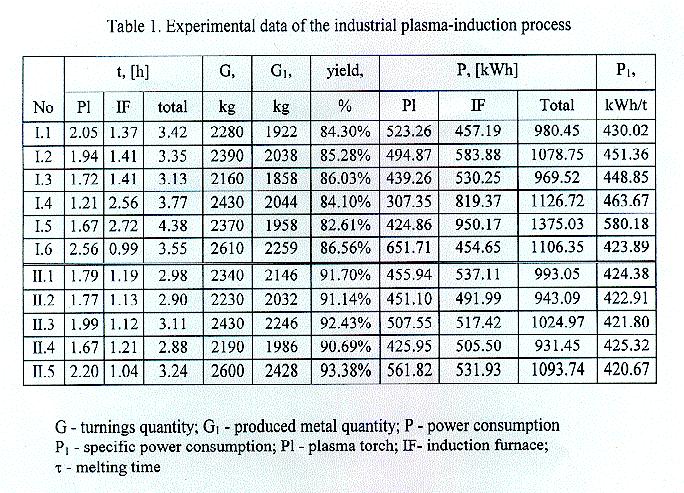
The first series of experiments cover 6 melts (I.1-I.6) which processed 14240 kg turnings and
obtained 12079 kg bronze ingots. Due to nonmetal impurities and lubricants the average yield is 85.25%. The average specific power consumption is 444 kWh/t (except melt No I.5).
The second series of experiments treat 5 melts (II.1-II.5) ~ which 11790 kg of turnings are processed and 10838 kg of bronze is produced. Bronze turnings are preliminary subjected to ferromagnetic separation and heating under 250°C in order that lubricants are burnt: Mixing of the total processed turnings quantity reaches their constant bulk weight and chemical composition. The average yield is increased to 91:87% and the average specific power consumption is decreased to 423kWh/t.
Due to the preliminary turnings processing the total melting time is cut with 12.22%; the specific power consumption - with 4.63% and the chemical composition of the produced bronze is stabilized - aluminium oxidation is 0.8 % and iron contents varies in the limits allowed for the certain bronze brand.
CONCLUSIONS
- The possibility for an effective industrial bronze turnings melting in 2.5 tons plasma-induction furnace and the production of conditional bronze ingots is proved.
- Depending on preliminary processing and bronze turnings bulk weight:
- the yield is 90-93 %;
- the specific power consumption for melting is 420-464 kWh/t;
- the melting time for 1 ton charge is 1.2-1.55 h.
- Under actual organization and technology conditions in Kremikovtsi Ltd preliminary charge processing is advisable - averaging out, magnetic separation and lubricants removal.
REFERENCES
- Mihovsky, M.; Tzonev,. Tz & Lucheva, B. Reconstruction of a Working Industrial 2.5-tons Induction Furnace into a Plasma-induction one, In Proceeding of 8th International Metallurgy and Materials Congress,. Istanbul, Turkey, 1997, pp.1429-1434.
- Mihovsky, M.; Tzonev, Tz & Lucheva, B Transferred Arc Plasma Torch For Metallurgical Applications TPP-5, 5th European Conference on Theý~rrýal Plasina Processes, St-Petersburg, Russia, 1998.
3. Mihovsky, M.; Tzonev, Tz. & Lucheva, B. High Speed Steel Turnings in Plasma-Induction Furnace by Argon-Nitrogen Plasma, In Proceeding of the 4th International Thermal Plasma Conference, Athens, Greece, July 15-18, 1996, pp. 519-525.
EXCITED HYDROGEN STATES AND CHEMICAL PHENOMENA ON A LIQUID SILICON TARGET UNDER A PLASMA TORCH
D. Morvan, F Krayem, J. Amouroux
Laboratoire de Genie des Procedes Plasma et Traitement de surfaces ENSCP 11 rue Pierre et Marie Curie 75005 PARIS, France
Silicon can be purified by an argon plasma torch under the action of oxygen and hydrogen radicals. Our goal is to understand the interaction of the hydrogen atoms produced by an RF plasmatorch with the liquid silicon at 2500 K.
In order to qualify the H-Si interaction the experimental study is developed in 3 steps:
The first step consists in an analysis of the Argon-H2 plasma by 0ES spectroscopy in order to determine the quantity and the different kinds of hydrogen atoms Ha, Hb, Hg, He, Hs, produced at 1 atmosphere in a 3 MHz plasma torch in an Argon-H2 mixture (7KW, 30 1/mn). These results point out that the strong electromagnetic fields transfers high energy level on molecular hydrogen and explain the formation of excited atoms of hydrogen but also molecular species as measured by Fulcher bands.
The second step consist to melt the silicon under the plasma torch of Ar-H2-O2 gas mixture in order to purify the material. The OES permits to control the atomic emission line close to the surface including OH, Si and atomic impurity emission such as A1, Ca, Mg, Na.
The third step need to qualify the Deuterium concentration in the bulk of the silicon crystal by the Deuterium analysis through its diffusion at high temperature and low pressure from the silicon target. Mass spectroscopy and MET imaging point out the high temperature trapping of Deuterium (1100 K) in the crystal defects.
To compare these analysis with atomic hydrogen flow we point out that the high excited state of hydrogen atoms are responsible of the specific chemistry an the production of a cristalline silicon which is such of an alloy SiH without dangling bounds. Properties of a such thermal plasma open new routes for other applications as hydrocarbon pyrolysis or waste treatment of chlorinated compound.
| Chairman: | R. Henne
J.F. Coudert
|
EFFECT OF METAL PARTICLES OXIDATION DURING THE APS ON THE WETTABILITY
G. Espie(1), P. Fauchais(1), B. Hannover(2), J.C. Labbe(1), A. Vardelle(1)
(1)SPCTS, University of Limoges, 87060 Limoges Cedex, FRANCE
(2)LASTSM, University of Rouen, 76821 Mont Saint Aignan Cedex, FRANCE
Investigations are conducted to study the oxidation of in flight iron particles during the
Atmospheric Plasma Spraying (APS). The particles are cooled by an inert gas (argon) and
collected in a experimental set-up, especially developed for this purpose. With this set-up,
more than 90 wt% of the particles leading to the coat is collected. Methods such as XRD,
Mössbauer spectroscopy and SEM-EDX are used to determinate the amount and the
distribution of oxide formed. The results indicate that Würstite (FeO) is present at the surface
but also in the core of the particles. This oxide phase represent about 15 wt% of the collected
particles and is stable over time. Sessile drop studies of molten iron on alumina and zirconia
substrate are carried out to simulate the wetting of oxidized iron particles during coating
formation. It is found that oxidation of iron particles during the APS has a significant effect on
the observed contact angles. A decrease of the contact angle is observed in the case of
oxidized iron particles.
FUNDAMENTAL CONSIDERATION IN THE HIGH RATE DEPOSITION OF BARIUM HEXAFERRITE THICK FILMS
USING AN INDUCTIVELY COUPLED PLASMA PROCESS
Patrick R. Taylor and Edgar E. Vidal
Plasma Processing Laboratory, University of Idaho
ABSTRACT
This paper describes a potential process for a one step high rate (>400 nm/min)
deposition of BaFe12O19 thick film using an inductively coupled plasma (ICP) deposition
technique. In the proposed ICP process, a mixture water and dissolved barium and iron salts are
fed into the plasma flame and vaporized, the vapors are carried by the plasma flame to a water
cooled, controlled temperature, rotating substrate where BaFe12O19 deposits as a film. The
authors have experience in employing the ICP technique to deposit films; for example, we have
deposited crystalline diamond thin films with effective control over crystal orientation and grain
size. The main objective of the research program was to develop a fundmanetal understanding of
the potential of ICP technique to deposit thick BaFe12O19 films at a deposition rate higher than
400 nm/min with the following characteristics: (1) uniform grain size, (2) crystal orientation
perpendicular and longitudinal to the film plane, and (3) smooth surface. Additionally,
experiments were performed in an attempt to reduce the substrate temperature below 500oC. The
research program provides fundamental information on a deposition process that may be
integrated into practical production facilities.
The ICP process offers a pure reaction environment because it is an electrodeless system.
It also produces a large volumetric flame and is a high temperature source for deposition. In this
method, deposition of components in film form depends on their vapor pressure, feed rate,
temperature gradient, momentum gradient, substrate position from the ICP and substrate
temperature. An ICP reactor has been designed and experiments have been performed. Based on
our experience, experiments were designed and performed to optimize various process variables
including feed rate, plasma flow rate, substrate temperature, substrate position from the ICP, etc.
A mathematical model for the flow and temperature fields was formulated and solved to gain a
general insight into the flow geometry and temperature distribution from the section of the
injection probe to the level of the substrate surface, and to estimate the behavior of the gas
boundary layer formed on the substrate to describe the mechanism of BaFe12O19 thick film
formation. The reactor has sufficient instrumentation to give the detailed information needed for
subsequent scale-up of the process.
Microstructure and chemical characterization of the deposited BaFe12O19 thick films
was performed (SEM, TEM, XRD, etc.). The morphology and roughness was measured using
atomic force microscopy. The magnetic properties of the film were determined using a vibrating
sample magnetometer while the noise spectra was obtained using a spectrum analyzer. All of this
equipment is available in our laboratory and department.
EXPERIMENTAL SETUP
The complete experimental setup is shown in Figure 1. It consists basically of three
sections: the power supply and ICP Torch, which includes the water cooling system; the reactor
and substrate holder; and, data acquisition devices, consisting of thermocouples, thermometers
and flowmeters.

The ICP torch is powered by a Lepel 100 kW Power Supply. It generates a RF current
with a frequency of about 3.4 MHz. The Inductively Coupled Plasma Torch is a TAFA Model 66.
It consists of a 3" id water-cooled quartz tube, surrounded by a solid 6 turn copper coil. It can be
operated up to 60 kW. The plasma gases (pure or mixed) are injected axially, radially and
tangentially through the top of the torch. Since the torch does not have electrodes, it is a very
clean energy source. The water-cooled cylindrical brass reactor, that holds the substrate holder, is
connected to a pair of oil-less vacuum pumps, that can maintain a pressure of 230mTorr (0.3 atm)
inside the reactor. The ICP torch, the reactor and feed probe are enclosed with a copper screen, to
"drain" the RF field generated by the torch to ground. It is important to mention that the feed
probe and the reactor itself are at the same bulk plasma potential, since no biased potential is
induced.
Currently two types of substrate holders are in use: a static substrate holder, and a
rotating substrate holder. The first does not allow realignment of its axis relative to the centerline
of the ICP torch, and does not permit rotation around its axis. This holder is used to evaluate
potential experimental variables, when uniformity of the film is not a concern. The rotating
substrate holder can be moved up and down along its axis in order to increase or decrease its
distance to the torch flame. Also the central axis can be offset from the torch centerline. The
substrate holder is rotated by means of a variable speed electric motor, which permits a uniform
deposition of the vaporized materials. By controlling the speed and precursor feed rate, it is
possible to control the thickness and morphology of the films.
The reactor itself consists of a cylindrical water-cooled brass jacket, with a copper coil
cooled top flange that also acts as support for the ICP torch. It also has two view ports along its
side and two access ports, one of which is used by a pressure gauge. The bottom flange
accommodates the substrate holder and the exhaust pipe that goes to the vacuum pumps. This
bottom flange also has two ports for the cooling water used by the copper coils that cool the gases
before they exit the reactor. The precursors are fed through a 13.5" long water cooled nebulizing
feed probe, located on top of the ICP torch. The end of the probe can be positioned anywhere
along the torch, allowing the operator to control the residence time of the feed in the plasma
flame. The liquid precursor is fed in the nebulizer using a perilstatic pump, where it is finely
dispersed in a stream of oxygen/argon mixture.
A series of experiments have been performed to produce barium ferrite films. Vycor glass
was selected as one of the substrate materials due to its high thermal shock resistance, and high
softening temperature. Substrates were polished and cut by the manufacturer. The substrates are
cleaned before the experiments using ethanol. Pretreatments that have been used include the
deposition of ZnO in the same ICP reactor prior to the deposition of the barium ferrite. The
substrate is placed on the water-cooled substrate holder after being cleaned. The substrate holder
is then placed underneath the reactor chamber, ensuring that it is vacuum tight. Argon is bled into
the reactor through the torch in order to flush the air out of the system. The vacuum pumps are
turned on and the pressure adjusted. The plasma power and plasma gas flow rates are varied,
since they determine the substrate temperature during the deposition. Also the plasma gas
composition has been varied from pure argon to an argon-oxygen mixture, in order to study the
effect of the oxygen potential on the film produced.
It has been found that the best condition for producing BaFe12O19 is at 30 kW using Ar as
plasma gas. Oxygen is used for nebulizing the precursor solution, which is rich in Ba compared to
the stoichiometric requirements. The film formed is crystalline. Amorphous films that are
produced are subjected to annealing at 800 C for 2 hours in an oxygen atmosphere the BaFe12O19
crystallizes.
A mathematical model for the heat, mass and momentum transfer in the deposition
chamber has been formulated and solved. The model is being used to help redesign the reactor
for more uniform deposition.
CONTROL ON LINE OF LEAD AND ZINC EVAPORATION IN THE TREATMENT
BY TRANSFERRED ARC OF FLY ASHES FROM WASTE INCINERATOR
S. Bernard, P. Fauchais, J. Jarrige, J. P. Lecompte, P. Denoirjean
L.M.C.T.S.,CNRS E.S.A. 6015, Equipe Plasma, Laser, Materiaux, Faculte des sciences de Limoges, 123, av. A. Thomas-87060 Limoges Cedex
Tel : (33) 05 55.45.74.39 , fax : (33) 05 55 45 72 11 , E-mail : Chercheurs.plm@Unilim.fr
Scientific theme : 11. Waste Treatment and On-line Controls in Connection with Environmental Regulations
Key words : fly ashes, evaporation, transferred arc, zinc, lead, ICP analysis.
Due to their high temperature (15000°C), energy densities (up to 109 W/m3) and heat fluxes (more than 10g W/m2) transferred arcs are particularly suitable for waste destruction in general and especially that of fly ashes from waste incineration (REFIOM). These REFIOMs contain heavy metals such as Cd, Zn, Pb... as chlorides, sulfates, nitrates... and their storage in landfills will be no more permitted after 2000 because these products are leachable. One solution to this problem is to transform them in an inert glass. This is achieved by adding glass forming materials to the REFIOMs melted in a crucible by a transferred arc working in an inert atmosphere. The resulting inert glass traps the residual pollutants while the evaporated volatile metals are collected in specific filters. However, it is mandatory to understand how the volatile poilutants are evaporated in order to achieve a full treatment of REFIOMs.
The study of the evaporation of lead and zinc salts contained im REFIOMs is very complex due to their synergetic effects. So, a. model of REFIOM which composition could be easily changed is studied to simulate the REFIOM composition and the specific role of zinc or lead salts. To achieve this model, zeolithe matrix composed of 87 wt% of silicon oxide and 13 wt% of alumina is impregnated by chlorides, sulfates and nitrates corresponding to 2.5-7.5 wt% of heavy and, or volatile metals such as lead or zinc. This model allows to follow separately each salt evaporation and to characterize its evaporation rate in the plasma reactor. A second step, consists in studying the synergy between lead and zinc and also between nitrates and chlorides or chlorides and sulfates... At least, this study has to be completed by comparing our model to real REFIOMs.
 This study has been started in a laboratory sized plasma reactor (power lower than 30 kW). The doped zeolithes are treated (see figure 1) in a graphite crucible disposed in a water-cooled controlled atmosphere chamber where they are melted by a transferred arc stabilized by an argon flow (20 slxn). Evaporation control on line is achieved with an I.C.P. analysis system which allows to follow continuously and simultaneously the concentration of the different studied elements.
The sampling gas is picked up in the reactor with a 8 mm tube at 100 mm from the arc axis. A peristaltic pump working with a flow rate of 0.2 slm drives the sampling gas to the I.C.P. The response time of this analysis sytem is about 20 s.
 Emission spectroscopy technique allows to
analyse light, emitted by the RF piasma of the ICP,
with a monochromator (Jobin-Yvon HR1000) equipped with a photomultiplier. The used atomic lines
to follow lead, zinc and chlorine in the ICP are given in table 1.
Emission spectroscopy technique allows to
analyse light, emitted by the RF piasma of the ICP,
with a monochromator (Jobin-Yvon HR1000) equipped with a photomultiplier. The used atomic lines
to follow lead, zinc and chlorine in the ICP are given in table 1.
The I.C.P. signal during the treatment of the REFIOM model is proportional to the gaseous phase of the traced element: It allows to optimize the arc current to obtain a full treatment. The current, to achieve the full evaporation of lead, must be higher than that used for zinc, i.e. more than 400 A, against only 300 A for zinc. Full treatment was typically obtained after 10 minutes for zinc salts, and 20 minutes for lead salts when initial cation concentration was of the order of 5 wt% in a load composed of 50 g of doped zeolithes and 40 g of CaO. CaO is used to reduce molten bath viscosity.
The I.C.P. signal is integrated on the treatment time and normalized to compare zinc, lead and chlorine evaporations. Such measurement cofirm too that the treatment time increases with the initial cation concentration and allow to show that the total concentration of the evaporated element is proportional to the initial metal mass into the doped zeolithes before the treatment The evaporation speed of the zinc, and lead is characterized. When stationary working parameters are achieved (constant pressure, voltage and arc current), lead evaporation rate is nearly constant whereas zinc evaporation rate seems to decrease exponentially.
Chlorine evaporation rate is characterized when this anion is associated with zinc or lead. To achieve that, Ca0 additives have to be supressed because of the Ca I emission line (422.670 nm) interfering with the unique sensible Cl I emission line (422.634 nm). This study shows that the evaporation rate of chlorine is the same as that of the associated cation.
Residual metal concentration in the resulting glass is measured by X-rays fluorescence spectrometry. Full treatment is, considered to be achieved when it is no more possible to detect zinc or lead by X rays fluorescence in the glass. The fluorescence limit of detection, in our case, is less than few, ppm.
This study confirms that transferred arc is particularly suitable for an efficient evaporation of volatile substances (zinc) and heavy metals (lead) The experimental setup used allows to estimate the conversion efficiency of the process and check that the glass is inert. Zinc and lead could be totally evaporated and then collected to be recycled.
PLASMA DECONTAMINATION OF DEPLETED URANIUM OXIDE FROM STAINLESS STEEL SURFACES
John M. Veilleux and Mohamed S. El-Genk
University of New Mexico, Albuquerque, NM 87130
E.P. Chamberlin, C. Munson, and J. FitzPatrick
Los Alamos National Laboratory, Los Alamos, NM 87544
EXTENDED ABSTRACT
The cost of decontamination, treatment, long term storage, and monitoring of transuranic waste in the
United States in 1997 dollars has been estimated at over $28,000/m3, compared to $1,800/m3 for low level
radioactive waste1 . Transuranic waste is defined to be any alpha emitter with an atomic number greater
than 92, a half-life over 20 years, and an activity of 3700 Bq/g or greater. Plutonium and americium waste
contaminated objects are examples of transuranic waste. Therefore, there is a significant incentive to reduce
the quantity of this waste. Possible options include treatment to reclassify transuranic waste to low level
waste; volume reduction; or better yet a total or partial removal and full recovery. Unlike mechanical
scrubbing and water jet techniques, RF plasma is more effective for removal and recovery of trace
radionuclides from surface crevices, can be operated remotely, and provides a better margin of safety for
the operator.
Early experiments2 demonstrated that etching of Pu and PuO was possible in CF4/O2 RF plasma. But little
data was provided on the effect of various parameters with plasma immersion time, such as the absorbed
power and pressure of the process gas. Therefore, there was a need to continue this work to better quantify
the usefulness and limitations of using RF plasma glow discharge as an effective decontamination technique
for transuranic waste. The objective of this work is to quantify the effects of gas pressure and absorbed
plasma power on the etching of depleted UO2 from stainless-steel using RF glow discharge. A series of
single effect experiments were conducted with NF3 gas, in which the pressure was varied from 10.8 40 Pa
and the absorbed power from 25 to 210 W.
EXPERIMENTAL SETUP
The 13.56 RF plasma reactor consisted of a 0.125-m3 aluminum chamber for processing and a fume hood
mounted recovery system for pumping the chamber during plasma immersion experiments (Figure 1). The
measured DC sheath voltage ranged from 0.1 to 500 V at absorbed power of 25 210 W, respectively.
The NF3 gas flow rate was operated between 3 and 18.5 standard cubic centimeters per minute (SCCM),
resulting in plasma gas pressures varying between 10.8 to 40 Pa, respectively. The stainless steel mounted
(0.7958 cm) amorphous depleted UO2 samples (4.8 g/cm3) each contained 129.4 Bq total uranium (89.5%
238U) or 2.36x10¹⁹ molecules of 238U. Quantification of the samples' activity following plasma immersion
was performed using liquid scintillation counting3 with alpha/beta discrimination to minimize alpha particle
self-shielding and hi energy beta particle confounding (215.3 Bq) from 234Th and 234Pa daughters of 238U.
The glow in the chamber during processing had a magenta color typical of NF3 discharges. The glow was
brightest near the antenna at all pressures, filled the entire chamber at and below 17 Pa, and was brighter at
17 Pa than at 10.8. At higher pressure, the glow region shrunk towards the antenna, and was surrounded
by a dark region extending from the grounded walls of the chamber to the glow discharge edge.
RESULTS AND DISCUSSION
NR, the activity of uranium removed from the substrate surface normalized to the initial activity, is plotted
in Figure 2 versus the immersion time at 17 Pa and 50 W. The data closely follows an exponential function
of the form

In this equation, NR,max is the asymptotic or maximum fraction of UO2 molecules etched before reaching the
end point, t is the plasma immersion time, and t is the characteristic etch time. The end point, as defined in
this work, is when all detectable UO2 has been etched away or the etch rate becomes almost zero, with UO2
in the sample only partially removed. The etch rate of UO2 , J(t), can be expressed as:

The term (NR,max/t), or J0, is the initial etch rate at t=0 (0.0182 min-1 in Figure 2). The etch rate J
approaches almost zero after ~4-5 characteristic etch times.
The self-limiting nature of the etch process is demonstrated in the above two equations by the term
 . This term represents the blocking effect of the UO2 surface during processing to further
reaction with the atomic F generated in the bulk plasma to form a volatile UF6; it varies from unity at t = 0
to zero at the end point.
Results showed that etching of UO2 was strongly dependent on the absorbed power and on pressure to a
lesser extent (e.g., Figure 3 and Figure 4). At and above 50 W and 17 Pa, complete removal of all
detectable UO2 was achieved. At 25 W, however, the etch reaction was blocked, causing the etch rate to
become almost zero, before the complete removal of UO2 could be achieved. The etch rate increased
monotonically with pressure when the absorbed power ~100 W or greater. At lower power, however, the
etch rate increased with pressure up to ~23 Pa4 then decreased with further increase in pressure. The
measured etch rates ranged from 1.4 to 7.4 µm/min. . This term represents the blocking effect of the UO2 surface during processing to further
reaction with the atomic F generated in the bulk plasma to form a volatile UF6; it varies from unity at t = 0
to zero at the end point.
Results showed that etching of UO2 was strongly dependent on the absorbed power and on pressure to a
lesser extent (e.g., Figure 3 and Figure 4). At and above 50 W and 17 Pa, complete removal of all
detectable UO2 was achieved. At 25 W, however, the etch reaction was blocked, causing the etch rate to
become almost zero, before the complete removal of UO2 could be achieved. The etch rate increased
monotonically with pressure when the absorbed power ~100 W or greater. At lower power, however, the
etch rate increased with pressure up to ~23 Pa4 then decreased with further increase in pressure. The
measured etch rates ranged from 1.4 to 7.4 µm/min.

REFERENCES
- 1Allen, R.P. and R.F. Hazelton, "Conversion of Transuranic Waste to Low Level Waste by DecontaminationA Technical and Economic Evaluation", Battelle Technical Report PNL-5315, Dec. 1984.
- 2 Martz, J.C. and D.W. Hess, "Demonstration of Plutonium Etching in a CF4/O2 RF Glow Discharge", J. Nucl.
Mater., Vol. 182, p.277, 1991.
- 3Packard Model 2550 TR/AB Liquid Scintillation Counter with Alpha/Beta Discrimination.
- 4El-Genk, M. S., H. H. Saber, and J. M. Veilleux,, "Analysis and Modeling of Decontamination Experiments of Depleted Uranium Oxide in RF Plasma", Proc. Int. Sym. on Heat and Mass Transfer
Under Plasma Conditons, Antalya, Turkey, 19-23 April 1999.
ANALYSIS OF POLLUTED SURFACES BY TIME RESOLVED LASER INDUCED BREAKDOWN SPECTROSCOPY
S. Morel1, L. Dudragne1, P. Adam1, J. Amouroux~2
(1) Centre d'Etudes du Bouchet de la direction des centres d'Expertise et d'essais B.P. N°3, 91710 Vert-le-Petit, FRANCE
(2) Ecole Nationale superieure de Chimie de Paris, Laboratoire de Genie des Procedes Plasmas 1l, rue P. et M. Curie, 75231 Paris Cedex 05, FRANCE
During these last fifteen years, the technique of Time REsolved Laser Induced Breakdown Spectroscopy (TRELIBS) has become an established method for real time analysis of surfaces, liquids and gases as well. Focusing powerful laser pulse on a surface produces the vaporization of a small amount of the sample, then induces, near the focal region of the lens, a high temperature plasma. By using spectral and time resolved plasma emissions, the elemental composition of the material can be determined.
The interest of this method is mainly due to the many advantages it has to solve problems of in-situ and quasi real time analysis :
- multielement detection ability
- no need for a sampling system
- only optical components are used therefore avoiding air pollution
- remote analysis capability
Currently, the TRELIBS method is particularly well suited for field-based monotoring and for metallic element analysis of solid surfaces (steels, alloys, Pb in paints. . . )
Our objective is to show that the chemical warfare detection adsorbed or absorbed on surfaces can be achieved by this method. Our study takes place in a project to conceive a reliable and transportable field apparatus driving to identification of the main heteroatoms (fluorine, chlorine, sulfur, . . . ) in polluant agents at a very weak concentration (106 g/g). A previous study has shown a 20 ppm (w/w) detection limit threshold in air for atomic elements such as fluorine or chlorine.
First measurements were carried out on polymer targets whose composition is known : Teflon for detection of fluorine and PVC for chlorine. We identified the different parameters which control the plasma formation and the atomic emission intensity : the laser power, the lens focal length, the sample location, the number of accumulated spectra and clearly the physical properties of the material. The results we got allowed us to qualify a protocol for plasma formation and spectral acquisition for the detection of those elements.
In parallel a geometrical study permitted us to evaluate the size and the reproducibility of the plasma pulse to pulse. Moreover, observation of laser impact with SEM shown that this method is quasi non-destructive:
Nowadays we are working on toxic simulant adsorbed on paints. On such samples, we are able to identify the main atomic lines of chlorine, fluorine, sulfur and phosphorus. Our goal is now to perform a quantitative detection in order to reach lower thresholds requested because of the high toxicity of chemical warfare agents.
|
